Hi all,
My sincerest apologies for the long stretch of silence from my side. It was very busy the last few weeks and the envelopes I ordered for sending the PCB's took a very long time to arrive due to a issue with the shipping company.
I now have received the envelopes and am preparing the shipping as we speak. So it shouldn't be too long now.
Thank you for your patience and not if your not patient 😉😎
Best wishes,
Maarten
Dear all,
I sent all the PCB's on Monday. So they should be arriving on your doorstep over the coming week(s).
Thank you all for your patience! I know it has been quite the wait...
I sent all the PCB's on Monday. So they should be arriving on your doorstep over the coming week(s).
Thank you all for your patience! I know it has been quite the wait...
Package received yesterday, beauties!
In the BOM C9 has to be C11 i found. .
Also in the schematic D1=D2, D2=D4, D3=D1, D4=D3 compared to the pcb.
Not important but can be handsome...
Thanks Maarten.
Got them too! Thank you very much, Maarten!
And now... Shop the BOM!
Inviato dal mio D5803 utilizzando Tapatalk
And now... Shop the BOM!
Inviato dal mio D5803 utilizzando Tapatalk
Mfly,
Do you have a build guide for these boards? Just want to make sure there are not already some tweaks and improvements you've made to them. 🙂
Thanks,
Rick
Do you have a build guide for these boards? Just want to make sure there are not already some tweaks and improvements you've made to them. 🙂
Thanks,
Rick
Hi there! I'm putting together... Anyone has got it completed to show a pic, just for reference, before I'm blowing my home? 😀
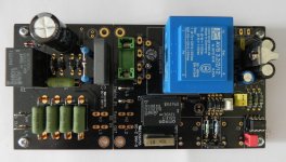
finished but not connected
Hi ghiglie, i made and tested 2 of them. I found that when i touched the switch contacts the circuit went on and off. I added a 0.1uF over the 555 V+ but didnot help. Then i added a 4.7nF capacitor parallel on R2. This fixed it. I use a low drop regulator and a 12V transformer as you can see in the picture. I also added a second fuse in series with the primary windings for securety. Regards, Loek
Hi there! I'm putting together... Anyone has got it completed to show a pic, just for reference, before I'm blowing my home? 😀
Hi ghiglie, i made and tested 2 of them. I found that when i touched the switch contacts the circuit went on and off. I added a 0.1uF over the 555 V+ but didnot help. Then i added a 4.7nF capacitor parallel on R2. This fixed it. I use a low drop regulator and a 12V transformer as you can see in the picture. I also added a second fuse in series with the primary windings for securety. Regards, Loek
Attachments
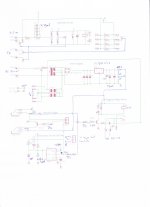
Hi ghiglie, i made and tested 2 of them. I found that when i touched the switch contacts the circuit went on and off. I added a 0.1uF over the 555 V+ but didnot help. Then i added a 4.7nF capacitor parallel on R2. This fixed it. I use a low drop regulator and a 12V transformer as you can see in the picture. I also added a second fuse in series with the primary windings for securety. Regards, Loek
Thanks Loek for your schemas and pic! I'll save them for reference. Nice idea about the fuse - if I get to source that easily, I'll take out the bridge. What LDO reg are u using?
Thanks Loek for your schemas and pic! I'll save them for reference. Nice idea about the fuse - if I get to source that easily, I'll take out the bridge. What LDO reg are u using?
LM2940CT12 as in the schema. What do you mean with "take out the bridge"?
LM2940CT12 as in the schema. What do you mean with "take out the bridge"?
Ops, sorry, I noticed it after posting. Tnx! I'll ask you about other mods in PM.
I thought I had to bridge J1A and J2B, right?
- Home
- Group Buys
- Remote trigger, momentary switch, soft start PCB (for First Watt or other projects)