6/ 4,25 volts every time i change program. (at least cold and relay clicking).
That sounds correct although obviously in a working state when tested. The base going high turn Q10 on and that pulls pin 5 to ground. The inverted output on pin 6 should be high and that turns off Q13 removing drive to Q11 and the relay.
Pin 6 shows 0,06 volts at all times i changes program.
I just checked voltage at Q11 and all 3 legs showed -33 volts, this can´t be right, or?
I just checked voltage at Q11 and all 3 legs showed -33 volts, this can´t be right, or?
Last one for tonight 😉
Detail, detail 🙂 Millivolts matter.
If the emitter is at -33v which is a rail and the transistor is on (so the relay will be open and audio gets through) then the collector will be at very close to -33v because the transistor is 'saturated' as it is used as a switch. The base will be a little more positive than the emitter so around -32.4 volts.
I just checked voltage at Q11 and all 3 legs showed -33 volts, this can´t be right, or?
Detail, detail 🙂 Millivolts matter.
If the emitter is at -33v which is a rail and the transistor is on (so the relay will be open and audio gets through) then the collector will be at very close to -33v because the transistor is 'saturated' as it is used as a switch. The base will be a little more positive than the emitter so around -32.4 volts.
If pin 6 remains at essentially 0 volts (logic level low) then the relay is powered and on which gives the approx -33 volts you are seeing on all the legs of Q11Pin 6 shows 0,06 volts at all times i changes program.
Pin 5 should be 'high' in this case. The 'high' logic level should be close to whatever the supply on pin 14.
If the logic is permanently in that state then the relay is not muting the audio as it is powered and the contacts open.
Thanks. I have replaced the Q10, Q11 and Q13 without any difference, a while after power on the relay needs help, me switching programs, to close.
Can´t find any bad solder points either.
Can´t find any bad solder points either.
You have to break the circuit down into blocks and be 100% of the results before making a decision whether that section is OK.
When you say the relay needs help... it doesn't... its not failing to pull in in, its actually not letting go.
Pin 5 of IC1 has to be the first place to make a decision. Does the relay always work correctly when it sees the appropriate logic level. That tells you if the problem is before or after that point.
Ok, power switch on, no volts at pin 5, after a few seconds the relay clicks and 4,25 volts at pin 5.
Changing programs the relay clicks every time and 4,29 volts at pin 5.
After half an hour to 45 minutes the relay wont click when i change programs, still 4,29 volts at pin 5.
Why does the relay stop working, when it works perfectly fine at first?
Changing programs the relay clicks every time and 4,29 volts at pin 5.
After half an hour to 45 minutes the relay wont click when i change programs, still 4,29 volts at pin 5.
Why does the relay stop working, when it works perfectly fine at first?
That makes sense. 4.25 volts on pin 5 gives 0 volts on pin 6 which turns on Q13 and finally the relay. These are essentially steady state voltages.Ok, power switch on, no volts at pin 5, after a few seconds the relay clicks and 4,25 volts at pin 5.
Changing programs the relay clicks every time and 4,29 volts at pin 5.
I have a suspicion that your meter is possibly not responding quickly enough to show a short duration change in logic level. When the relay mutes during program change it will only be for a very short time duration. We need to prove if that is the case or not. In other words is there a short duration logic change and the meter isn't seeing it or have we a real problem before pin 5.After half an hour to 45 minutes the relay wont click when i change programs, still 4,29 volts at pin 5.
Do you have a scope to measure these voltages. If not then I'm going to suggest you try an LED and series resistor to make a simple logic probe and then look for brief changes in level. A high brightness LED and 10k should work. You would easily see the LED go on and off.
If you use an LED and resistor we would have to look at the outputs of the chip rather than inputs (to avoid loading because some are at a high impedance).
When the fault has occurred and the relay is not responding can you try just shorting out Q10 (literally with a screwdriver or bit of wire 🙂) from collector to emitter and see if the relay clicks on and off in response to the short. That will pull the voltage on pin 5 down to 0 volts and should change the state of all the following logic and relay drive state. If it clicks on and off every time you do that when the fault is present then we know the relay and transistors and that particular invertor in IC1 is OK.
Every time i change program and the relay clicks my Fluke DMM shows a short duration change in logic level (zero volts at the click).I have a suspicion that your meter is possibly not responding quickly enough to show a short duration change in logic level. When the relay mutes during program change it will only be for a very short time duration. We need to prove if that is the case or not. In other words is there a short duration logic change and the meter isn't seeing it or have we a real problem before pin 5.
And yes, shorting emitter and collector on Q10 makes the relay click and voltage at pin 5 goes from 4,29 volts to 1,25 volts while it clicks.
OK, lets just pursue that a bit more.
When the fault appears do you then not see this change in level.
First thing is that pin 5 voltage should go to zero (0.000 volts) when you short C to E. Look at the circuit. The emitter is grounded and the collector goes direct to pin 5. So pin 5 has to see zero volts in that situation. Lets just clear that one up first and if pin 5 really does not go to zero we need to look why. Could be the diagram is incorrect or something else......And yes, shorting emitter and collector on Q10 makes the relay click and voltage at pin 5 goes from 4,29 volts to 1,25 volts while it clicks.
And this is pin 5 you are looking at?Every time i change program and the relay clicks my Fluke DMM shows a short duration change in logic level (zero volts at the click).
When the fault appears do you then not see this change in level.
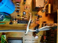
If i´m not mistaken, and i may very well be, #5 pin is marked yellow and #14 is marked red.
And yes, shorting emitter and collector on Q10 makes the relay click and voltage at pin 5 goes from 4,29 volts to 1,25 volts as long as it´s shorted.
Also, every time i change program and the relay DON´T clicks my Fluke DMM shows a short duration change in logic level (zero volts).
And yes, shorting emitter and collector on Q10 makes the relay click and voltage at pin 5 goes from 4,29 volts to 1,25 volts as long as it´s shorted.
Also, every time i change program and the relay DON´T clicks my Fluke DMM shows a short duration change in logic level (zero volts).
Attachments
Is this correct? I have a feeling it's not right when i´m looking at the schematics and the PBC.
Maybe i´m shorting the wrong legs?

Maybe i´m shorting the wrong legs?
That's correct.If i´m not mistaken, and i may very well be, #5 pin is marked yellow and #14 is marked red.
Yes, however if you short collector to base instead you would see a voltage on the collector. I think that might be what has happened.Had to make sure i shorted E and C on Q10 and this would be legs 1 and 2?
Make it easy 🙂 Switch the unit off and just measure on ohms to see which lead of the transistor goes to ground and which goes to pin 5 (which should be the middle one).
This is very important.Also, every time i change program and the relay DON´T clicks my Fluke DMM shows a short duration change in logic level (zero volts).
If pin 5 shows a change in logic level (high to low, low to high) then that should be mirrored on pin 6. Can you check this. Remember pin 6 will be the opposite level to pin 5 because those are logic invertors in the chip.
Something puzzles me in the circuit diagram but don't loose sight of the fact we know the actual circuit must be correct because it works when correct.
It is Q14 marked as a 2SA1115
If pin 6 goes high to 5 volts then that puts 5 volts on the emitter and that would effectively clamp the output from pin 6 to ground via B/E junction. It could never rise above around 0.7 volts. It doesn't compute. Is Q14 really a 2SA1115 or is it a self biased transistor like Q13 or is there a missing resistor on the diagram from emitter of Q14 to pin 6.
Anyone else reading this? What do you think?
These transistors are very critical because they are not like ordinary NPN and PNP ones.
Ok, leg #3, which would be the base according to the specs of the RN1203, goes to ground 0,2 Ohms.
The diagram however shows that leg #1, the emitter should go to ground.
Leg #2 collector goes to pin #5.
Pin #6 shows 0,067 volts goes to 0 when relay clicks and then back.
Q14 is marked 115 which would be the 2SA1115?
The diagram however shows that leg #1, the emitter should go to ground.
Leg #2 collector goes to pin #5.
Pin #6 shows 0,067 volts goes to 0 when relay clicks and then back.
Q14 is marked 115 which would be the 2SA1115?
If you have fitted the transistors as they were originally then that has to be correct because it has worked in the past and does work until the fault appears. The data sheets normally show the lead view looking from underneath. I wouldn't worry to much over this if they are fitted as originally because that must be correct.
Check this result again. If pin five is at 5 volts pin six should be zero.
When pin five is at zero volts pin six should be at 5 volts. If pin six just makes it to 0.067 volts with zero volts on pin five then something is either pulling that voltage down or the chip has an issue.
------------------------
This is Q14 and why I'm puzzled. I've done this quick simulation to show you what happens with it as drawn. The voltage source at the left is pin 6 generating 5 volts but with a limited current. The base/emitter junction of Q14 clamps this voltage because the junction is like a diode. Something is in error with the circuit diagram or the type of transistor. Any PNP would behave like this and the 2SA1115 looks to be an ordinary transistor. So this part of the circuit diagram definitely doesn't compute.

This doesn't look right. 0.067 is just 67 millivolts and that will not switch anything. Pin 6 has two possible states, 5v and 0v with nothing in between. So that needs looking at and checking. As I said, pin 6 must be the opposite of pin 5 at all times.Pin #6 shows 0,067 volts goes to 0 when relay clicks and then back.
Check this result again. If pin five is at 5 volts pin six should be zero.
When pin five is at zero volts pin six should be at 5 volts. If pin six just makes it to 0.067 volts with zero volts on pin five then something is either pulling that voltage down or the chip has an issue.
------------------------
This is Q14 and why I'm puzzled. I've done this quick simulation to show you what happens with it as drawn. The voltage source at the left is pin 6 generating 5 volts but with a limited current. The base/emitter junction of Q14 clamps this voltage because the junction is like a diode. Something is in error with the circuit diagram or the type of transistor. Any PNP would behave like this and the 2SA1115 looks to be an ordinary transistor. So this part of the circuit diagram definitely doesn't compute.
I was shorting the wrong legs, shorting the correct legs, C and E the 4,29 voltage goes to 0,001 volts at pin 5.First thing is that pin 5 voltage should go to zero (0.000 volts) when you short C to E. Look at the circuit. The emitter is grounded and the collector goes direct to pin 5. So pin 5 has to see zero volts in that situation. Lets just clear that one up first and if pin 5 really does not go to zero we need to look why. Could be the diagram is incorrect or something else......
I shorted the C and E on Q10 for 0 volts at pin 5, then i got 4.81 volts at pin 6.When pin five is at zero volts pin six should be at 5 volts. If pin six just makes it to 0.067 volts with zero volts on pin five then something is either pulling that voltage down or the chip has an issue.
Well, not zero but 0,067 volts. Close enough?Check this result again. If pin five is at 5 volts pin six should be zero.
No, its no where near.Well, not zero but 0,067 volts. Close enough?
It has to swing between 0 and 5 volts.Pin #6 shows 0,067 volts goes to 0 when relay clicks and then back.
5 volts turns Q13 off while anything lower than around 3 volts will turn on Q13 and apply power to the relay.
Then you say this 🙂
I shorted the C and E on Q10 for 0 volts at pin 5, then i got 4.81 volts at pin 6.
Which implies it does switch.
Powered the unit on this morning and everything works fine, relay mutes at every program change.
I´ll check again in about half an hour and see if it still works.
And, pin 6 shows 0,067 volts, goes to 0 when relay clicks changing program and then back to 0,067 volts.
Pin 6 is 0,067 volts at all times except forcing the relay closed by shorting C and E on Q10, then it is 4,80 volts.
If pin 6 should show 0 volts, what makes it show 0,067 volts?
Is this why the relay wont work after a while?
- Home
- Source & Line
- Analog Line Level
- Relay control?