Sweet! I’ll maybe play a vinyl and keep my thermocouple on the resistors to see how it performs.
One thing I noticed is that it was a little light on the bass response. The coupling capacitors between the preamp tube and the power tube is 0.47uF. If I increase this a bit would it increase the bass response?
Also, when I ordered my replacement tubes there were no 6N2 tubes in stock so I ordered a 12AX7. It looks like the 12AX7 is the pretty much same tube that can be run from 12.6VAC filament voltage at pins 4&5, but if I connect the center tap to ground it should still work with 6.3VAC. Does this look right?
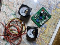
Finally, I got a small VU meter driver board with a couple of meters, just so I could add something nice to the front panel when I build the enclosure. I’d like to have the levels increase when I turn the volume knob, so I was thinking of running a small capacitor between the preamp outputs and the driver board input. This should allow for the AC signal to pass through to the driver board without the power tube anode voltage crossing over. I attached a picture of the driver board and the meters. This should be okay, right? What capacitance value would work? I’m thinking like 0.22uF or smaller.
One thing I noticed is that it was a little light on the bass response. The coupling capacitors between the preamp tube and the power tube is 0.47uF. If I increase this a bit would it increase the bass response?
Also, when I ordered my replacement tubes there were no 6N2 tubes in stock so I ordered a 12AX7. It looks like the 12AX7 is the pretty much same tube that can be run from 12.6VAC filament voltage at pins 4&5, but if I connect the center tap to ground it should still work with 6.3VAC. Does this look right?
Finally, I got a small VU meter driver board with a couple of meters, just so I could add something nice to the front panel when I build the enclosure. I’d like to have the levels increase when I turn the volume knob, so I was thinking of running a small capacitor between the preamp outputs and the driver board input. This should allow for the AC signal to pass through to the driver board without the power tube anode voltage crossing over. I attached a picture of the driver board and the meters. This should be okay, right? What capacitance value would work? I’m thinking like 0.22uF or smaller.
Attachments
Are you measuring the heater voltage at the valve terminals?
Are you getting about the same cathode voltages for each channel, and what is the EL34 cathode voltage?
It is better to markup a schematic with all your voltage readings, and post that, as just describing one or two measured levels does not provide much confidence to readers that you have the rest of the circuitry performing correctly. And a photo or two can help to identify if connections are appropriate or suspect.
Do you not want to connect the VU board input to the speaker terminals?
That’s a great idea. I’ll go ahead and upload a copy of the schematic with all of the voltages annotated. I was planning on connecting the VU driver board before the output stage as I read somewhere that it might mess with output transformers as extra load. I’m also running one channel for testing as my tube on the channel was having some issues. New tubes should be delivered this Saturday.
What is the VU driver circuitry/schematic? I would have guessed that to have a relatively high impedance (as far as a speaker output) ac coupled input.
If required you can a series resistor of 1K or higher when you connect the VU driver circuit to the output transformer. Your transformer won’t even notice the extra load.
Regards, Gerrit
Regards, Gerrit
Unfortunately I don’t have a schematic of the driver board. Listened to a vinyl on the tube for a good 40 minutes or so with a couple of thermocouples (one attached to the resistors that were blowing, the other aimed at my power tube) and it performed flawlessly. Temp on the tube equalized at around 270°F and the resistors didn’t get over 115°F. I’ll put a 1K resistor in series to the output side of the transformer and run the VU’s tomorrow.
I finally understand what people say about the clarity of single ended amps - that blew me away.
I finally understand what people say about the clarity of single ended amps - that blew me away.