Hello,
My old Rega turntable has motor gone bad so I replaced it with below motor which was the cheapest that I could find.
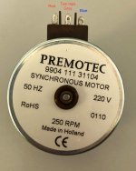
DataSheet (Motor Type: 9904 111 31104)
https://www.farnell.com/datasheets/1765731.pdf?_gl=1*zww2k5*_gcl_au*MjEyMTY0OTk5NS4xNzMwMjgzNjMz
It is 220v 16mA 250rpm motor.
I am based in Australia and main voltage is 240v so I used 1.6K ohm Resistor to drop the voltage down to 220v and used 0.1uf X2 type Capacitor for direction of the motor.
However, the motor runs clockwise one time but when I turn off and turn on again it runs anti-clockwise and whenver I turn off and on, it is random 🙄
And, the torque is very weak and when I put the light platter on then it is struggling to turn.
It is brand new motor from Element14 and I would like to check if I did anything wrong before sending it off.
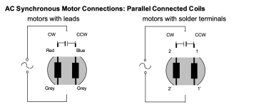
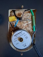
I attached diagram from Datasheet and actual rough soldered connection before heatshrink them properly.
Please correct me if I did anything wrong.
Thank you.
My old Rega turntable has motor gone bad so I replaced it with below motor which was the cheapest that I could find.
DataSheet (Motor Type: 9904 111 31104)
https://www.farnell.com/datasheets/1765731.pdf?_gl=1*zww2k5*_gcl_au*MjEyMTY0OTk5NS4xNzMwMjgzNjMz
It is 220v 16mA 250rpm motor.
I am based in Australia and main voltage is 240v so I used 1.6K ohm Resistor to drop the voltage down to 220v and used 0.1uf X2 type Capacitor for direction of the motor.
However, the motor runs clockwise one time but when I turn off and turn on again it runs anti-clockwise and whenver I turn off and on, it is random 🙄
And, the torque is very weak and when I put the light platter on then it is struggling to turn.
It is brand new motor from Element14 and I would like to check if I did anything wrong before sending it off.
I attached diagram from Datasheet and actual rough soldered connection before heatshrink them properly.
Please correct me if I did anything wrong.
Thank you.
Attachments
220v - 250v the motor doesn't care. It is the frequency of your mains supply that matters.
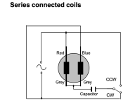
As a rule, these should be wired with the coils in series for maximum torque and stability.
Use a 220nF Class Y capacitor. If you use a class X or X2, they can fail short circuit and may damage the motors windings. It looks like you have a class X but I cannot read the value.
All you have to do then, is select the direction and spindle size for the RPM of the turntable.
Attachments

@JonSnell Electronic Thank you very much.
Just to double check, is the motor that I mentioned ok to connect in series?
According to the data sheet, the motor 9904 111 31 104 is only Parallel connection with 0.1uf capacitor to use.
Just to double check, is the motor that I mentioned ok to connect in series?
According to the data sheet, the motor 9904 111 31 104 is only Parallel connection with 0.1uf capacitor to use.
No need, as already mentioned above, 220, 230, 240, 250 are all the same !!I am based in Australia and main voltage is 240v so I used 1.6K ohm Resistor to drop the voltage down to 220v ...
That is possibly due to a wrong value of running capacitor for the auxiliary winding. Ideally, the two winding currents of a single phase induction motor need to be at 90* (electrical angle) to obtain maximum torque. However, sometimes the capacitor used gives a wrong angle that reduces the torque. But since the motor is able to start, I guess it's just about a different value of start/run cap and the motor is probably ok.the torque is very weak and when I put the light platter on then it is struggling to turn....It is brand new motor from Element14 and I would like to check if I did anything wrong before sending it off.
@JonSnell Electronic Thank you again. I put the correct cap value so not sure why torque is weak and it runs both clockwise and anti-clockwise when turn on and off. (scratching head).
Maybe I did wiring wrong?
Here is what I did (as shown on the photo on first post)
Pretty simple connection and not sure if I did anything wrong. (scratch head).
Here is what I did (as shown on the photo on first post)
- AC Main Neutral go to Grey of motor (both grey motor taps are connected)
- AC Main Active connected to 1.6Kohm resistor then connected to one end of Pwr Switch
- The other end of Switch wire connected to both legs of 0.1uf capacitor
- both legs of cap goes to red and blue tap of motor
Pretty simple connection and not sure if I did anything wrong. (scratch head).
That does not sound right.The other end of Switch wire connected to both legs of 0.1uf capacitor
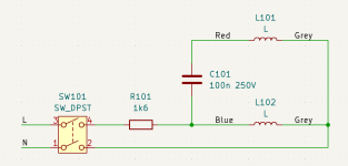
This circuit should be AC Live to switch
Switch to resistor
resistor to capacitor and one winding
other winding to other end of capacitor
two grey wires to AC neutral
@davidsrsb Thank you very much. It makes sense. I will make adjustment when I am back home and report the findings.
Just rewired as instructed and it still the same.
What I found strange is that it seem working if the platter taken off from subplatter but when I put the platter on the subplatter then motor acts strange and it goes back and forth, not spinning clockwise constantly.
Is this because there is not enough torque so acting crazy?
What I found strange is that it seem working if the platter taken off from subplatter but when I put the platter on the subplatter then motor acts strange and it goes back and forth, not spinning clockwise constantly.
Is this because there is not enough torque so acting crazy?
@davidsrsb Thank you very much for those tips. I just tried swap red and blue and it is almost same (actually a bit worse).
Here are voltage measurement.
Red-Grey = 232v
Blue-Grey = 232v
Red-Blue - 0.07v
I think that there is something wrong between Red - Blue voltage because it is almost Nil.
Here are voltage measurement.
Red-Grey = 232v
Blue-Grey = 232v
Red-Blue - 0.07v
I think that there is something wrong between Red - Blue voltage because it is almost Nil.
The idea is that the voltages across the two windings should be 90 degrees out of phase, so that the two windings create a rotating magnetic field that the motor rotor follows.
Hence 220 x 1.414V
Your first photo showed a motor with tag terminals, not wires. I am puzzled how you map those tags to wire colour.
Hence 220 x 1.414V
Your first photo showed a motor with tag terminals, not wires. I am puzzled how you map those tags to wire colour.
The idea is that the voltages across the two windings should be 90 degrees out of phase, so that the two windings create a rotating magnetic field that the motor rotor follows.
Hence 220 x 1.414V
Your first photo showed a motor with tag terminals, not wires. I am puzzled how you map those tags to wire colour.
Here is the photo with text. Left-Red, Right-Blue and middle two taps are Grey as far as I understand.
Attachments

- Question was are you able to check the cap ?
- You show two different motors, Premotec and Allied,
Now, why do you expect a different result from an identical
motor ? Please enlighten us. Not sure what is going on here.
@as_audio How do I check the cap? can I check the cap with multimeter?
Yes, I showed premotec one from internet for demonstration which is same as Allied motor.
I do not understand what you mean by different result from an identical motor. The issue is same starting from the beginning. Motor does not turn clockwise when platter is on but moving back and forth.
Yes, I showed premotec one from internet for demonstration which is same as Allied motor.
I do not understand what you mean by different result from an identical motor. The issue is same starting from the beginning. Motor does not turn clockwise when platter is on but moving back and forth.
My impression was you changed the Premotec for Allied or the other way round.
If not - what is that example doing here ?
In post 1 you write that the original Rega "motor gone bad" but how do you know,
what are the symptoms ?
Show us the original motor and its wiring. Try to describe the whole picture without
adding confusion.
The cap can not be checked with the multimeter - except for a short ..
- Home
- Source & Line
- Analogue Source
- Rega Motor Wiring. What have I done wrong?