Hi,
Two weeks ago I purchased a vintage Tecnics SA-5370 in great condition. Minimal usage signs, all original under the hood and everything working as it should.
It is a unit produced in '77 as the hiper popular Marantz 2238 and 2252 that have similar specs just its sels for one fifth of their price.
Last weekend I replaced the electrolytics on the psu, pre and power amplifier and now it produces extra clean sound. In the next opportunity I plan to replace the elcos also on the tuner and phono board and to replace the rectifier with four ultra fast diodes.
What I don't like about it is it's tonal balance. Compared to my (also refurbished) NAD 3033 it is a lot brighter with the midrange sounding to forward. The treble is also a bit brighter but it doesn't bother me that much. The lows are nice and tight and quite extended but they are covered by the shouting midrange.
So my question is whether there is a way to influence the general tonal balance of the amplifier by changing the capacitor values ,changing the buffer transistors or even changing the power transistors??? Any other ideas are welcome.
Or perform a loopback test using RMAA via the headphone out (careful with volume, you don't want to be toasting your soundcard input!). In the results, pay special attention to both frequency response and channel separation. (Could be a bad ground connection somewhere, too.)
Using "ultra fast diodes" isn't going to net you any improvements.
I don't know why people even bring that up, they must have "heard something" on the internet.
As for "tonal balance", there are tone controls used for that, if too much midrange.
Comparing two different makes of receivers doesn't mean one is worse than the other.
I don't know why people even bring that up, they must have "heard something" on the internet.
As for "tonal balance", there are tone controls used for that, if too much midrange.
Comparing two different makes of receivers doesn't mean one is worse than the other.
The whole amplifier is a power stage with tone control in the power stage NFB. This forces some compromise; it also is sensitive to tone-part tolerances.
Sweep the frequency response to see how large the error is. But _IMHO_ this is a great garage amp, not a primary listening-room amp.
Sweep the frequency response to see how large the error is. But _IMHO_ this is a great garage amp, not a primary listening-room amp.
Since my knowledge in electronics is very basic and I don't own any pro equipment i took a chance at this idea. I just did the loop back test via the tape monitor.Or perform a loopback test using RMAA via the headphone out (careful with volume, you don't want to be toasting your soundcard input!). In the results, pay special attention to both frequency response and channel separation. (Could be a bad ground connection somewhere, too.)
As I see from the result it rolls off quickly below 1khz. On the other hand the THD is at 0,0041, not bad for 42 year "garage amp"

Will replacing the ceramic capacitors around the tone controls help here?
Here is the result with the tone controls in the middle position and no loudness used:
Attachments

Using "ultra fast diodes" isn't going to net you any improvements.
I don't know why people even bring that up, they must have "heard something" on the internet.
As for "tonal balance", there are tone controls used for that, if too much midrange.
Comparing two different makes of receivers doesn't mean one is worse than the other.
Wiseoldtech, the reason I intend to replace the old rectifier is because i replaced the filter capacitors with cans with bigger value that I had on hand. Since they will probably draw higher surge current, for safety reasons I need rectifier diodes with higher current rating, and while I'm at that point why not try the ultra fast ones. The cost is the same.
Congratulations, you just failed the null test.Since my knowledge in electronics is very basic and I don't own any pro equipment i took a chance at this idea. I just did the loop back test via the tape monitor.
The tape loop usually contains no more than a few switch contacts and passives. It is as such unsuited to test the frequency response of the amplifier. It should also give near-perfect test results for the same reason.
Your playback/recording setup clearly still has some issues. Make sure that any and all processing on the playback and record side is disabled (effects, noise reduction, whatever), that the sample rates are set up correctly and identically everywhere, and that you are not mixing What You Hear with line-in or somesuch.
I have seen such "wiggles" in FR when some sort of effects was still enabled.
Hang on, there are ceramic caps in the tone control? As in C503-510? Those should definitely be replaced with films in the long run, and of no timid voltage rating either (I'd say 63 V min). If you can make polypropylene fit, use those, otherwise polyester is OK, I guess.Will replacing the ceramic capacitors around the tone controls help here?
Anyway, sort your measurement setup out first so you can document things as-is. Ideally you will also want to make an attenuator setup (e.g. 22k / 1k or something) so you can measure at high level without frying your line-in. A 1 Vrms level (+/-) should not be a challenge for an integrated amp like that. Mind you, it does give you an opportunity to determine its output noise level, assuming you have a reference for input level.
C0G/NP0 ceramic caps are perfectly fine for a tone-control. Not all ceramic caps use ferroelectrics.
Replacing a heatsinked bridge rectifier with 4 non-heatsinked diodes is not usually a great idea thermally, and ultra-fast are _not_ the ones to use, soft-recovery perhaps, but standard rectifier diodes are fine. Rectifier diodes need large pulse ratings, much larger than you might expect.
The specs say the frequency response should extend to 10Hz, so clearly some electrolytic coupling caps are completely shot.
Wiseoldtech, the reason I intend to replace the old rectifier is because i replaced the filter capacitors with cans with bigger value that I had on hand. Since they will probably draw higher surge current, for safety reasons I need rectifier diodes with higher current rating, and while I'm at that point why not try the ultra fast ones. The cost is the same.
That is a widespread practice, but it makes no sense technically. Increased capacity in the PSU filter capacitors can undermine the stability of other components, even on some tracks (weak, compared to the cables) of the PCB.
Is that the engineers calculated the appropriate value and the cost department forced them to reduce it? In these times, it could be, but in those years I doubt it.
Rod Elliott has looked at this in quite some detail.
In short, the difference in steady state is quite minimal, just the power-on transients may need some consideration, depending on how "soft" the transformer output is (which serves as a current limiter).
It's moot anyway, as a look into the parts list reveals "polyester" for all of the caps in question. Not the highest of high end, but neither is this receiver... anyway, good enough.
Fast rectifiers do have their advantages, as they generate a great deal less RF (switching) noise which you have to get rid of with parallel capacitors (Z701, Z702) and/or snubbers otherwise.
In short, the difference in steady state is quite minimal, just the power-on transients may need some consideration, depending on how "soft" the transformer output is (which serves as a current limiter).
True, but NP0s beyond about 1 nF seem to be quite exotic. They would also be a bit on the large side.C0G/NP0 ceramic caps are perfectly fine for a tone-control. Not all ceramic caps use ferroelectrics.
It's moot anyway, as a look into the parts list reveals "polyester" for all of the caps in question. Not the highest of high end, but neither is this receiver... anyway, good enough.
Agreed on thermals. Not sure what the original diode bridge would have been rated at. I'd guess maybe 6 A, minimum 5 A, maybe 10 A.Replacing a heatsinked bridge rectifier with 4 non-heatsinked diodes is not usually a great idea thermally, and ultra-fast are _not_ the ones to use, soft-recovery perhaps, but standard rectifier diodes are fine. Rectifier diodes need large pulse ratings, much larger than you might expect.
Fast rectifiers do have their advantages, as they generate a great deal less RF (switching) noise which you have to get rid of with parallel capacitors (Z701, Z702) and/or snubbers otherwise.
I would not trust his measurement setup as far as I can throw it at this point.The specs say the frequency response should extend to 10Hz, so clearly some electrolytic coupling caps are completely shot.
Last edited:
I am aware that the measurementsI took might not be precise, aldough I took all the filters and sound effects before taking them.
Afterwards I did realized that the tape monitor bypasses the tone controls.😕
Today I took a read at the following article:
Amplifier Tone Control
Than I realized that the SA-5370 has the Baxandall tone controll circuit with slightly different values of the resistors and the capacitors. The beauty of the vintage equipment is that it is so modification friendly.
I opened the hood and increased the Value of the C505 and 506 up to 1uf (that is the smallest cap I have at the moment ) I turned it on and all the low frequencies that were missing previously were now present but slightly exaggerated. It felt like I hit a bingo 🙂.
So I suppose I will change the ceramics around the tone controls with some nice foil caps and lower the 1uf at C505/6 a bit so the bottom comes in balance with the rest of the frequencies.
Concerning the rectifier, I plan to use the Fairchild RURP 3060, these are rated 30A. Will these be ok?
There must be something still amiss. Frequency response must look super smooth, not like a ragged mess, and it would be quite unlikely to drop off like a rock below 100 Hz. What do you use for a sound device? Could you perhaps make screenshots of the playback and recording devices' relevant properties pages (Alt + PrintScreen)? This is one of those situations where I'd probably have it sorted out fairly quickly if I were to be sitting in front of the computer. (If you really can't get it sorted, this might be a case for good ol' TeamViewer.)I am aware that the measurementsI took might not be precise, aldough I took all the filters and sound effects before taking them.
Along with most everything else... There's almost literally just the source selector switch there.Afterwards I did realized that the tape monitor bypasses the tone controls.😕
I hope you can still find some adapters to tap off from the headphone output.
Again, these are not ceramics. They are MKT (polyester) film caps, at least if the real device matches its service docs.So I suppose I will change the ceramics around the tone controls with some nice foil caps and lower the 1uf at C505/6 a bit so the bottom comes in balance with the rest of the frequencies.
I would also not change anything before you haven't taken any decent measurements.
Substantially oversized even. A Grundig V5000 (100W/4R / 70W/8R, so rather more powerful) used two sets of 6 A diodes = 12 A. (With a set of 10000µF caps each.) 15 A seems plenty for yours.Concerning the rectifier, I plan to use the Fairchild RURP 3060, these are rated 30A. Will these be ok?
This unit shipped with 10000 µF / 45 WV caps. 8200 µF is sufficient for a 20 Hz lower power bandwidth limit into 2x 4 ohms. As such, an upgrade in capacitance seems quite unnecessary if the old caps still happen to be good (which after 40+ years may or may not be the case, depending on parts quality and the unit's previous life - looking at the rail voltages with an AC-coupled oscilloscope input or checking the caps with an ESR meter should give some clues). Do you know what comes in home theater receivers these days? 6800 µF, at a nominal power of 2x 130 W / 6 ohms, with 7 power amps.
Last edited:
All the Technics equipment that I've had on my service bench over the decades was built with quality, and designed just as nicely.
There was no need to ever "upgrade" or "modify" those units, sound-wise.
Proper servicing brings back the excellent performance and reliability.
There was no need to ever "upgrade" or "modify" those units, sound-wise.
Proper servicing brings back the excellent performance and reliability.
Sgrossklass thank you for your generous input and suggestions. I spent last night considerable time troubleshooting. I did the measurements trough the
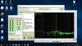
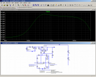
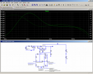
headphone jack a couple of times with different settings but again with no positive result. I think the hardware limitation of my computer doesn't allow proper measurement to be taken. So I give up. Attached you can find a screenshot of the RMAA while taking the test and two test rapports, one using the windows default drivers and one using the soundcard own drivers.
About the rectifiers you are definitely right, Ill leave the old one be as it is, as it is rated at 20A if I can guess from its product code - 2SHB 20-
Yesterday evening, while taking a look at the tone control resistors, I noticed that almost all of them were off the specs by margin bigger than the suggested +- 10% . Could this be the source of the tonal unbalance? Do the carbon resistors degrade with time?
Attachments
Well I think I found the problem.
I measured again all the resistors from R505 to 516.
R505/6 are 10k in place of 12k (a bit under the secs. margin )
R513/14 measured 22k instead 120k, and this is probably manufacturing mistake than degraded resistor.
The rest of the resistors are in the margin of -10% but slightly inconsistent between the channels.
Anyway I'm gonna replace all the caps and resistors around the tone controls and see if this will solve the unbalanced tone.
This manufacturer has always used 5% resister as a minimum in audio parts of circuits. If 22k is measured where 120k should be, the res is replaced wrongly (red-red-orn <> brn-red-ylw). During final test at factory, a misplaced res would be detected and replaced. Matshushita is sincere in this proces (I worked for them).
If res-values are a bit of spec, the amp might have served for years in the tropics. The Service Manual is your guide; I would undisputably rely on it.
If res-values are a bit of spec, the amp might have served for years in the tropics. The Service Manual is your guide; I would undisputably rely on it.
As a long-time service tech, one of the things I do is inspect PC boards for tampering.
I've got a keen eye to spot parts that might have been replaced by some amateur for whatever reasons.
I can tell if the solder isn't "factory original" which tells me someone's been in the unit.
I'd be suspicious of that 22K resistor before removing it by checking its soldering against the other parts on that tone board.
Wisdom and age may be on to something. 😉
This is what would happen if you took the pot setting that gives a flat response with 120k and put in 22k instead:

Looks very much like the OP's problem, I'd say.
Substituting the 0.12µ for a 1µ then yields this:
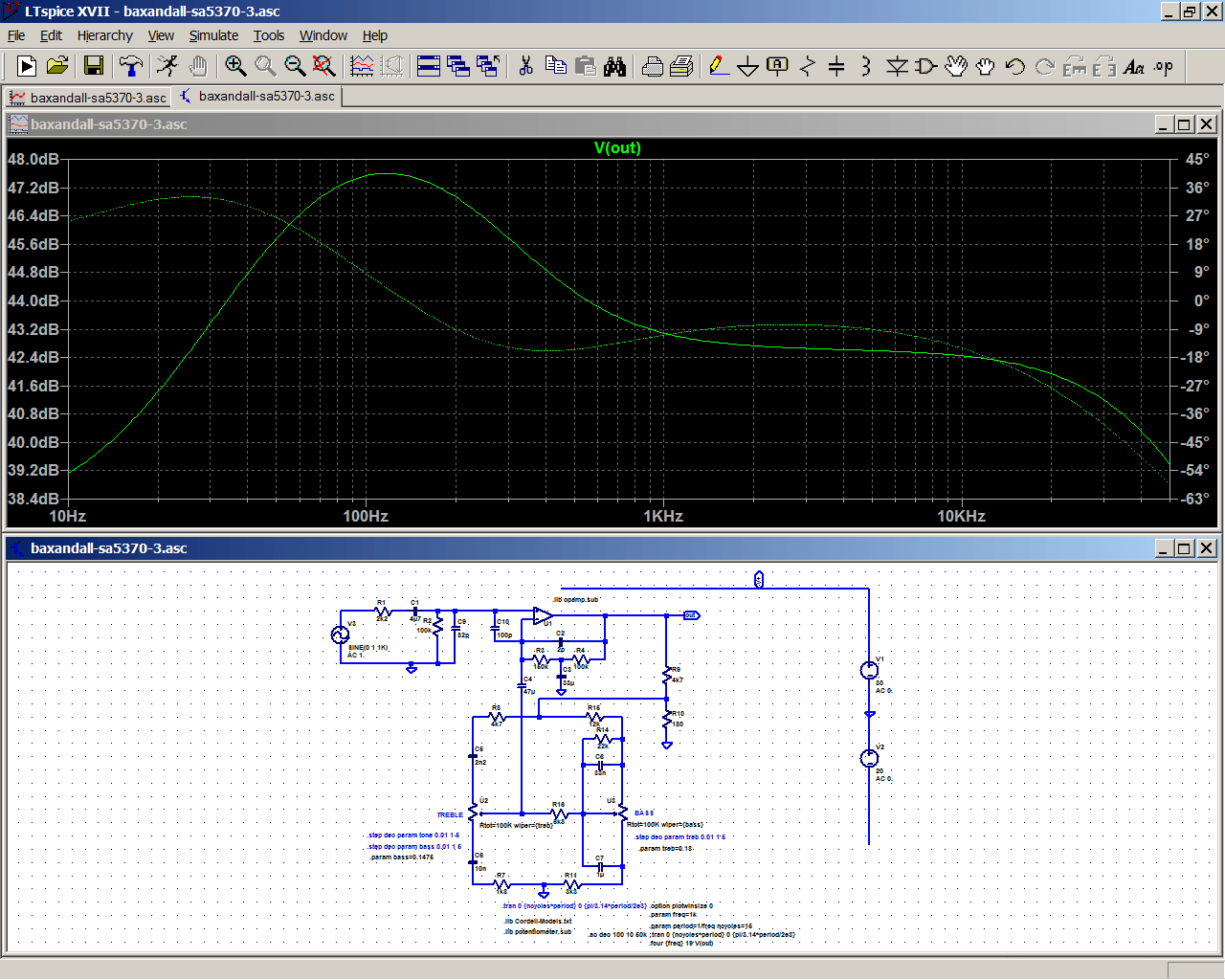
Erm... that's too much, dude.
The only reason for putting in a 22k that I can think of is that someone had to replace the bass pot. (Do bass and treble pots look different?) This is a 2x 100k reverse log pot (100kC), and optimum FR flatness occurs at a wiper setting of about 0.1475 in "normal log" terms, or -16.62 dB. I don't know much about antilogs, but from what I've seen of normal log pot measurements, midpoints tended to be around -26 dB, or 0.05. Guess where the flat position with the 22k is? Yep, 0.05.
Still, it should have worked like this. Maybe they did put in the wrong resistors at the factory after all? Otherwise, why would someone even touch these? Putting in modern metal film resistors? They don't look like modern-day blue 1% Yageos, do they?
Anyway, I got maximum flatness with stock values at slightly different settings for bass and treble - 0.1475 on the bass and 0.18 on the treble. You should be able to measure that - 14.75k in parallel with C505, and 18k between C501(-) and C509.
Now on to the misbehaving measurement setup... OP, what kind of computer (motherboard) and sound device even is this? The results sure look lousy. Those are not from using the headphone out though, are they?
This is what would happen if you took the pot setting that gives a flat response with 120k and put in 22k instead:
Looks very much like the OP's problem, I'd say.
Substituting the 0.12µ for a 1µ then yields this:
Erm... that's too much, dude.
The only reason for putting in a 22k that I can think of is that someone had to replace the bass pot. (Do bass and treble pots look different?) This is a 2x 100k reverse log pot (100kC), and optimum FR flatness occurs at a wiper setting of about 0.1475 in "normal log" terms, or -16.62 dB. I don't know much about antilogs, but from what I've seen of normal log pot measurements, midpoints tended to be around -26 dB, or 0.05. Guess where the flat position with the 22k is? Yep, 0.05.
Still, it should have worked like this. Maybe they did put in the wrong resistors at the factory after all? Otherwise, why would someone even touch these? Putting in modern metal film resistors? They don't look like modern-day blue 1% Yageos, do they?
Anyway, I got maximum flatness with stock values at slightly different settings for bass and treble - 0.1475 on the bass and 0.18 on the treble. You should be able to measure that - 14.75k in parallel with C505, and 18k between C501(-) and C509.
Now on to the misbehaving measurement setup... OP, what kind of computer (motherboard) and sound device even is this? The results sure look lousy. Those are not from using the headphone out though, are they?
Attachments
Last edited:
- Home
- Amplifiers
- Solid State
- Refurbishing a vintage Technics SA-5370