Pre order list
aradan - 2x TDA1541A shunt module (+5V/-5V/-15V)
vinyldehyde - 4x Red Baron 5.0, 2x TDA1541A shunt module (+5V/-5V/-15V), 2x +5V shunt module (+5V/+3.3V)
polaron - 4x +/- PS module, 2x TDA1541A Shunt module (+5V/-5V/-15V), 2x +5V Shunt module (+5V/+3.3V)
Mayday - 1x Red Baron 5.0, 2x DC Ref. Module
steveware - 3x Red Baron 5.0
robots - 1x Red Baron 5.0
galbucci - 1x Red Baron 5.0, 2x +/- PS module, 2x TDA1541A Shunt module (+5V/-5V/-15V), 2x +5V Shunt module (+5V/+3.3V)
gig - 1x Red Baron 5.0
Hi Lucas,
unfortunately i have no idea why you have the 1st issue with the Teradak X2. Mine runs perfect without problems with 16bit/44.1Khz and 3.3V at the RB.
Did you know witch sampling frequency comes out of the Airport Express I2S?
Best,
Oliver
Hi Oliver/ Red Baron community
I believe it's 44.1/16. Would the sampling frequency affect the attenuator operating voltage?
My Teradak is also running perfectly, just at 2.54v instead of 3.3v. Does anybody have any ideas why that might be? Could a component on the Red Baron board have died I wonder...a diode maybe?
Thanks
aradan - 2x TDA1541A shunt module (+5V/-5V/-15V)
vinyldehyde - 4x Red Baron 5.0, 2x TDA1541A shunt module (+5V/-5V/-15V), 2x +5V shunt module (+5V/+3.3V)
polaron - 4x +/- PS module, 2x TDA1541A Shunt module (+5V/-5V/-15V), 2x +5V Shunt module (+5V/+3.3V)
Mayday - 1x Red Baron 5.0, 2x DC Ref. Module
steveware - 3x Red Baron 5.0
robots - 1x Red Baron 5.0
galbucci - 1x Red Baron 5.0, 2x +/- PS module, 2x TDA1541A Shunt module (+5V/-5V/-15V), 2x +5V Shunt module (+5V/+3.3V)
gig - 1x Red Baron 5.0
nthall - 1x Red Baron 5.0, 1x TDA1541A Shunt module
Would the sampling frequency affect the attenuator operating voltage?
No.
Perhaps it will be a good idea to post your question to -ecdesings- thread, because he is the mastermind behind the circuit.
Best,
Oliver
You needed 20 pre-orders of the Red Baron 5.0 to order the PCB's?
Yes.
Yes.
I hope we get there soon 🙂
I've got one board populated and I have the parts for the second board either already here or on their way.
hi Oliver,
are there any reasons why you use smd caps in red baron v.5 pcb?
is it because the smd are better than the film caps at this positions?
so far i couldn't find any best reason about why using the film caps like mks mkp or smd caps like ceramic or mica, for those decoupling caps.
thanks.
are there any reasons why you use smd caps in red baron v.5 pcb?
is it because the smd are better than the film caps at this positions?
so far i couldn't find any best reason about why using the film caps like mks mkp or smd caps like ceramic or mica, for those decoupling caps.
thanks.
Last edited:

what about this one?
the supplier said it is 180nf mica (wima)
is it good/enough for decou positions?
thanks.
aradan - 2x TDA1541A shunt module (+5V/-5V/-15V)
vinyldehyde - 4x Red Baron 5.0, 2x TDA1541A shunt module (+5V/-5V/-15V), 2x +5V shunt module (+5V/+3.3V)
polaron - 4x +/- PS module, 2x TDA1541A Shunt module (+5V/-5V/-15V), 2x +5V Shunt module (+5V/+3.3V)
Mayday - 1x Red Baron 5.0, 2x DC Ref. Module
steveware - 3x Red Baron 5.0
robots - 1x Red Baron 5.0
galbucci - 1x Red Baron 5.0, 2x +/- PS module, 2x TDA1541A Shunt module (+5V/-5V/-15V), 2x +5V Shunt module (+5V/+3.3V)
gig - 1x Red Baron 5.0
nthall - 1x Red Baron 5.0, 1x TDA1541A Shunt module
Myint 67 2 x Red Baron 1x +5v shunt module (pls ship with aradan if possible )
__________________
Last edited:
Is this the latest when it comes to DEM etc?
I tried reading through this entire thread yesterday to get up to date with everything, it's a looong thread though.
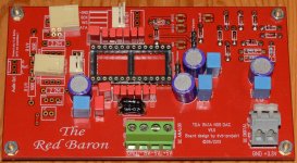
This is the board I ordered recently that will be parallel with the one on pre-order.
I've got all parts needed to fully populate the board should I want to except the 2SK216's as the ones I ordered were fakes(wrong pinout). Got my money back no questions asked though.
I got BEYSCHLAG 500R UXC0309-25 0.1% 1/2W (0.5W) 25ppm for the I/V, OS-CON SA for the 150uF, WIMA FKP2 for 2n2, VISHAY BC MKP380 for the 100nF, Holco's for 6K8 and Vishay's for the other resistors, followed the BOM for the decoupling caps.
I actually made the effort to match the 1N4148's, I had tons and figured it wouldn't hurt.
I tried reading through this entire thread yesterday to get up to date with everything, it's a looong thread though.
This is the board I ordered recently that will be parallel with the one on pre-order.
I've got all parts needed to fully populate the board should I want to except the 2SK216's as the ones I ordered were fakes(wrong pinout). Got my money back no questions asked though.
I got BEYSCHLAG 500R UXC0309-25 0.1% 1/2W (0.5W) 25ppm for the I/V, OS-CON SA for the 150uF, WIMA FKP2 for 2n2, VISHAY BC MKP380 for the 100nF, Holco's for 6K8 and Vishay's for the other resistors, followed the BOM for the decoupling caps.
I actually made the effort to match the 1N4148's, I had tons and figured it wouldn't hurt.
Attachments
Last edited:
aradan - 2x TDA1541A shunt module (+5V/-5V/-15V)
vinyldehyde - 4x Red Baron 5.0, 2x TDA1541A shunt module (+5V/-5V/-15V), 2x +5V shunt module (+5V/+3.3V)
polaron - 4x +/- PS module, 2x TDA1541A Shunt module (+5V/-5V/-15V), 2x +5V Shunt module (+5V/+3.3V)
Mayday - 1x Red Baron 5.0
steveware - 3x Red Baron 5.0
robots - 1x Red Baron 5.0
galbucci - 1x Red Baron 5.0, 2x +/- PS module, 2x TDA1541A Shunt module (+5V/-5V/-15V), 2x +5V Shunt module (+5V/+3.3V)
gig - 1x Red Baron 5.0
nthall - 1x Red Baron 5.0, 1x TDA1541A Shunt module
Myint 67 2 x Red Baron 1x +5v shunt module (pls ship with aradan if possible )
hi Oliver,
are there any reasons why you use smd caps in red baron v.5 pcb?
is it because the smd are better than the film caps at this positions?
so far i couldn't find any best reason about why using the film caps like mks mkp or smd caps like ceramic or mica, for those decoupling caps.
thanks.
Hi wengtech,
i modified active divider decoupling pads for better SMD 1210 caps soldering, because of a recommendation from -ecdesigns-, but you could also use the Wima MKS on the position.
-ecdesigns- said:Stacked foil PPS SMD caps that have very low inductance and very low mechanical foil resonance.
Conventional foil caps like the WIMAs consist of foil winding that's pressed into a flat shape (I opened some of these caps to have a look inside). This results in areas with high mechanical foil tension (curves) and low mechanical foil tension (flat area). This results in mechanical foil resonance. This basically creates conditions similar as with an electret microphone. The charged foil movement translates into unwanted ac signals that distort the DC bit currents.
Leaded caps also have higher inductance (increased resistance for RF ac signals). This in turn degrades decoupling effectivity.
Keep in mind that the active divider decoupling caps are used to suppress glitches from the electronic switches and ripple current from passive divider mismatch. Fundamental is at approx. 200 KHz, higher harmonics are also present. So RF / HF decoupling is required, this also means that every mm counts and shortest possible wiring is required.
Since the decoupling caps connect directly to the bit current outputs, the slightest ac ripple current on GND (> 61nA) will result in dynamic bit errors as unwanted ripple current is super-imposed on the DC bit current. The cap acts as low impedance and simply "pass on" the GND ripple. Thus the cap itself cannot prevent this.
This means that no other (supply or interference currents) must share decoupling cap GND return path.
I mounted the SMD caps underneath the DAC chip and routed GND for left and right decoupling cap group straight to pin 5 (AGND) thus preventing other GND currents to pollute the bit currents.
Best regards,
Oliver
Is this the latest when it comes to DEM etc?
I tried reading through this entire thread yesterday to get up to date with everything, it's a looong thread though.
This is the board I ordered recently that will be parallel with the one on pre-order.
I've got all parts needed to fully populate the board should I want to except the 2SK216's as the ones I ordered were fakes(wrong pinout). Got my money back no questions asked though.
I got BEYSCHLAG 500R UXC0309-25 0.1% 1/2W (0.5W) 25ppm for the I/V, OS-CON SA for the 150uF, WIMA FKP2 for 2n2, VISHAY BC MKP380 for the 100nF, Holco's for 6K8 and Vishay's for the other resistors, followed the BOM for the decoupling caps.
I actually made the effort to match the 1N4148's, I had tons and figured it wouldn't hurt.
Hi Mayday,
this is the actual and latest version (V5.0) from the Red Baron, yes.
Best,
Oliver
what about this one?
the supplier said it is 180nf mica (wima)
is it good/enough for decou positions?
thanks.
If you want to go with the SMD´s, please use the recommended in the BOM.

Thanks 🙂Hi Mayday,
this is the actual and latest version (V5.0) from the Red Baron, yes.
Best,
Oliver
And a big thank you for making these boards available for us.
I've got a couple of options for I/V resistors on the way (for parallel and single DAC) and I'm waiting for the last parts needed for the Borberly opamp 4 circuit using two Philips ECC86 and two pairs 2SK216/2SJ79.
As well as a pair of matched NOS russian PIO's that will be the output capacitors.
Is there anyone that has tried the Borberly design as output for a TDA1541A based DAC?
I'm quite eager to hear the combination:
WM8805/8804 - SM5814 - 2xTDA1541A - Borberly opamp 4.
I like the analog metric DAC with all parts carefully picked and passive I/V followed by a ECC86/2SK170 SRPP hybride stage...this new DAC has every potential to beat that by far.
Hey Oliver - Please put me down for:
- Shunt regulator module for TDA1541A (+5V, -5V, -15V)
- separate Shunt regulator module for additional parts (+5V)
- DC reference module
- TDA1541 mudule
- Reference TDA1541A DAC PS Module
I jumped on the Tube-I-zator PCB thread so I have that already.
Thanks,
Aguaazul
- Shunt regulator module for TDA1541A (+5V, -5V, -15V)
- separate Shunt regulator module for additional parts (+5V)
- DC reference module
- TDA1541 mudule
- Reference TDA1541A DAC PS Module
I jumped on the Tube-I-zator PCB thread so I have that already.
Thanks,
Aguaazul
- Status
- Not open for further replies.
- Home
- Group Buys
- "Reference" TDA1541A DAC with I2S-BUS architecture