The length in h:m:s is on the scale above. The total recording was about 2h 50min. The scale to the right is linear FS. Here zoom in dB-scale of the area arround the red box.

Interesting, thanks! Looks like there were no "islands of stability" during your measurements...
What was your entire signal path? In my setup the clocking of the soundcard between ADC and DAC makes a difference. Will do a similar long-term test with both variants (clocking of the soundcard via AES/EBU vs. WC) next.
What was your entire signal path? In my setup the clocking of the soundcard between ADC and DAC makes a difference. Will do a similar long-term test with both variants (clocking of the soundcard via AES/EBU vs. WC) next.
Thanks!
So we see impact on analog side of a couple of dB during a period of say 2 minutes but also slowly rising level of 1 dB over say an hour. Of course this is for 11,05 kHz / Fs/4 "situation" but it is also present at Fs/8, 16 etc but not to the same extent.
I would say that it is fair to state that the PLL in the DAM has negative consequences on the analog side. I would go so far that it might actually be detectable by ear. For a tone, no question but also for music. Maybe not in a A/B test but it actually might add a general "character" to the SQ of the product.
Stubborn like a drunk I still suggest a "Hi" mode where the PLL requires more of the source stability and does much less adjustments - for some there will be pops and clicks - sorry mate - used the "normal" mode or get another source.
//
Interesting, thanks! Looks like there were no "islands of stability" during your measurements...
What was your entire signal path? In my setup the clocking of the soundcard between ADC and DAC makes a difference. Will do a similar long-term test with both variants (clocking of the soundcard via AES/EBU vs. WC) next.
The signal path was:
Computer, USB to the RTX6001 Audio Analizer.
RTX SPDIF (Coax) out to the DAM with a Normundss input board.
DAM analog out recorded with RTX and back by USB to the computer.
The RTX uses a asynchronous XMOS USB interface which is clocked by the common ADC/DAC clock of the RTX. There is an isolator between the XMOS interface and the rest (especially the clocks). The RTX clocks are NZ2520SD (they behave, with respect to stability, like the unaltered SI514). The RTX-SPDIF-out comes from its XMOS board.
The Normundss input board connects the SPDIF with transformer and termination to the DAM, it was designed before the recommendation with the receiver was made.
... Of course this is for 11,05 kHz / Fs/4 "situation"
Fs was 192kHz for this measurement 😉
Clocking effekts schould be more visible at higher frequencys.
But... I made the same measurements a day before with 44 and 192 kHz, just at other levels and, more important, without simultanious frequency measurement. The 44kHz recording looks somehow worse.
The 192kHz recording has something like a long "island of stabillity" but then starts to oscillate.
44:

192:

But... I made the same measurements a day before with 44 and 192 kHz, just at other levels and, more important, without simultanious frequency measurement. The 44kHz recording looks somehow worse.
The 192kHz recording has something like a long "island of stabillity" but then starts to oscillate.
44:
192:
Here's 75 minutes of the DAM1021 clocked by the RME hdspe AES card which is in turn clocked by a DCS 904 via WC.
It was very similar to my last measurements: After a little more than 10 minutes things get stable and deviations are no worse than 0.2 dB. But after a little more than 25 minutes the "island of stability" ends and deviations intensify, reaching as much as 0.6 db.
Soeren, maybe you could chime in?
It was very similar to my last measurements: After a little more than 10 minutes things get stable and deviations are no worse than 0.2 dB. But after a little more than 25 minutes the "island of stability" ends and deviations intensify, reaching as much as 0.6 db.
Soeren, maybe you could chime in?
Attachments

Would all of this also hold for the dam1121? Despite reclocking after the FGPA and the Si570?
Its my understanding that the DPPL is common to all DAM so - Yes. Reclocking fixes jitter and thats good. This is not jitter. The performance here that we see is governed by software properties that affects this way beyond the HW clock performance - so for the discussed aspects, Si514 or 570 doesn't matter. But for jitter, Si570 is an improvement. But this is not about jitter 😉
//
//
Last edited:
Its my understanding that the DPPL is common to all DAM so - Yes. Reclocking fixes jitter and thats good. This is not jitter. The performance here that we see is governed by software properties that affects this way beyond the HW clock performance - so for the discussed aspects, Si514 or 570 doesn't matter. But for jitter, Si570 is an improvement. But this is not about jitter 😉
//
Very clear 10Hz, 20Hz.... to 100Hz degrading Jitter/spurious seen in given wave file 😀
As it goes with all synthesizer (digital PLL based) as PLL analog based 😀
hp
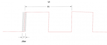
I dont know what you guys use as definition for jitter. I use timing errors less than 1/10 UI, UI being:
Intel
Description
The acronym UI stands for Unit Interval and it is a specification unit for jitter used to determine the maximum delta time of an arriving clock.
Clock signals have an average period, but any given transition can arrive slightly before or after an expected transition due to jitter. This delta time before or after an expected transition is calculated by multiplying the UI value by the average period.
For example, a 100 MHz clock has an average period of 10ns. If the maximum UI jitter = 0.025 UI, the maximum delta time will be:
10 ns x 0.025 UI = 250 ps (maximum delta time)
In equation form:
maximum delta time = average period x jitter (specified in UI)
Spurious is new tones right?
And for everybody to be happy - jitter, as per definition above and picture below, can of course also be described in the frequency domain as phase noise 🙂
//
Attachments
Last edited:
Jitter and phase noise are typically measured by two different instruments. Both instruments have their limitations. What Intel is concerned with is jitter as it affects bit errors, not close-in phase noise or other audible jitter effects. Thus, they use a definition appropriate to their needs.
Please note that the Intel reference was conceptual - the indicated time errors might or might not be relevant for audio. Your post seem to aim for your post count rather than adding to insight of the topic here.
//
//
The point is that for dacs, clock frequency changes that occur while music is playing is indistinguishable from phase noise in terms of how a dac sees it. If someone wants to make an arbitrary distinction between the two in order to simplify discussion, that's fine. But it doesn't mean someone else can't see the distinction as an oversimplification.
Last edited:
The phase noice that these frequency changes imposes might be high in level but they occur in the mHz territory - yes milli Hertz - when did you last see that measured? Not even Andreas timepod do that - this is long term. Shorter (er!!) term during when the Si is changed, the clock is probably pretty messy - Si say it takes 100 us to stabilise. We don't know how that looks.
Anyway, any serious EE would call whats going on, and is discussed here lately, Wander and not Jitter.
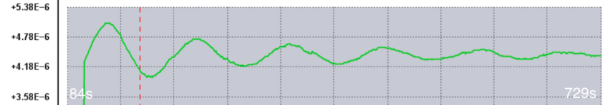
Looking at zfe measurements:

... we can see one low frequency component - thats the clock wandering - it makes about 5 cycles in approx 600 seconds - that would be 8,2 milli Hz.
.... there is an other low frequency component that is not resolved in this picture and that is the jitter from the clock at each point in time along the 600 seconds above. This is the jitter one measures with a Timepod and what is usually discussed as "close in phase noise". At 1 Hz or maybe even 0,1 Hz.
The "super duper mega atto close in noise" that is the first case above I don't even think can be measured by the Timepod - this would be dBc/Hz at 8,2 miili Hz - right? But if it could - yes, it would probably swamp the scarts...
//
Anyway, any serious EE would call whats going on, and is discussed here lately, Wander and not Jitter.
Looking at zfe measurements:
... we can see one low frequency component - thats the clock wandering - it makes about 5 cycles in approx 600 seconds - that would be 8,2 milli Hz.
.... there is an other low frequency component that is not resolved in this picture and that is the jitter from the clock at each point in time along the 600 seconds above. This is the jitter one measures with a Timepod and what is usually discussed as "close in phase noise". At 1 Hz or maybe even 0,1 Hz.
The "super duper mega atto close in noise" that is the first case above I don't even think can be measured by the Timepod - this would be dBc/Hz at 8,2 miili Hz - right? But if it could - yes, it would probably swamp the scarts...
//
Attachments
Last edited:
The "super duper mega atto close in noise" that is the first case above I don't even think can be measured by the Timepod - this would be dBc/Hz at 8,2 miili Hz - right? But if it could - yes, it would probably swamp the scarts...
//
There is no need to measure the phase noise at 8.2mHz from the carrier, you can easily calculate it by the Leeson's equation.
Just measure the phase noise at 0.1Hz (100mHz) from the carrier and then add 30 to 40 dBc for each decade.
Expect around 0dBC phase noise at 8.2mHz from the carrier from the SiLabs oscillators.
Yes, noise only.
Of course you need the Timepod or a more expensive gear like the E5052 and so on.
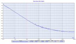
This is the phase noise plot of a Pierce pico gate oscillator using a ordinary AT-Cut crystal at 24.576 MHz.
The phase noise at 0.1Hz from the carrier is -54dBC.
It's almost 20dB better than the Crystek CCHD-957, that's at least 30dB better than the Si514.
As you can see in the 1/F3 region the phase noise degrades around 30dBc/decade (-116dBC at 10Hz, -85dBc ad 1Hz, -54dBc at 0.1Hz).
So you can predict the phase noise of the Si514 at 8.2mHz from the carrier like the following:
-54dBc at 100mHz from the carrier is the starting point, add 50dBc (20dB to the Crystek + 30dB to the Silabs).
You get a phase noise of 2-3 dBc at 8.2 mHz from the carrier from the Si514 that means noise only.
BTW, maybe the Timepod could measure the phase noise at 8.2mHz from the carrier, the only issue is that the measurement will take several days to allow the cross correlation averaging the results with a suitable number of samples.
Attachments
- Home
- Vendor's Bazaar
- Reference DAC Module - Discrete R-2R Sign Magnitude 24 bit 384 KHz