Is this hunting why this multitone doesnt look to great in the "bass"? Other DACs keep the grass well trimmed also at 20 Hz. But it's not clear if maybe USB was used and if so it would be not due to hunting.
https://www.superbestaudiofriends.org/index.php?attachments/upload_2020-11-17_19-36-12-png.23884/
//
Why would the clock related stuff even affect the bass? In that thread there is this alternative measurement by atomicbob btw. No issues whatsoever, near perfection:
https://www.superbestaudiofriends.o...20210103-dac2541-multitone-aes-bal-png.24485/
Yes, that looked better - thanks baten!
If you think about it - a 20 Hz tone will use 0,5s (20Hz!) /22us = 2272 samples to describe one whole 20 Hz tone. In order to PCM to work perfectly, every sample needs to be converted at the exact instance in time. But if the time instance start to sway... say that between 2 of the 2272 samples, the tome between them is not 22uS but 22,0005uS what happens in the conversion is that one get a small error in the recreated envelop of the 20 Hz signal. But here we also talk about errors that are say 120 dB down which is a very low level anomaly. Not easily heard - perhaps inaudible in most music playing scenarios and systems.
If you look at the "staple" for the low frequency tones in the multi-tone you linked to, you see that the base of the lower tones seem to be wider then the high ones. Ideally all of these staples should be just a line with no widening foot. This is due to frequency errors with a low frequency nature. If you look at the phase noise of an oscillator, you will see that it is much harder to make a clock not to exhibit low frequency deviations - this means that if you would sample the clock for its frequency/phase deviation from f0, you would see it being more often at 20 Hz off from f0 than 10kHz off from f0. In fact there is often a 40-70 dB difference between a real good clock (andrea) and an ordinary basic clock. There is a relation between jitter and phase noise. Both relate to an error in when a clock pulse should have occurred - just 2 different ways of looking at it. A clocks phase noise profile puts a watermark on the D/A conversed music.
Due to high(er) grade of low frequency components in a crystals error frequency distribution, this has an impact on the bass but it also can potentially have a more general impact in stability and air as every tone generated will be less "smeared".
Measurements of USB and s/pdif show traces of repeated components in these interfaces like e.g. the 400 Hz (?) repetitive sending of meta data on s/pdif can be traced to an artefact at 400 in the analog domain.
This is my understanding and I'm sure I will be corrected here soon if it is wrong 🙂
//
"...in the multi-tone you linked to, you see that the base of the lower tones seem to be wider then the high ones."
Don't forget the display is in log frequency, not linear frequency, which is what probably accounts for most of the appearance.
Could be the effects of phase noise may be more audible at low frequencies simply because of how human hearing works. So far as I know that's only a hypothesis, not proven.
Last edited:
Yes could be. The performance indicated in the measurement discussed is not "to shabby".
I was glad I wrote "Not easily heard - perhaps inaudible".
//
I was glad I wrote "Not easily heard - perhaps inaudible".
//
Last edited:
Soeren, could you please give us an idea when you will revise the DAM1021's re-clocking? It's been promised for a very long time now...
The fact that the sound quality changes with the source's properties is the only serious drawback left for me. With the right clock and filter the converter sounds truly magnificient.
The fact that the sound quality changes with the source's properties is the only serious drawback left for me. With the right clock and filter the converter sounds truly magnificient.
The fact that the sound quality changes with the source's properties is the only serious drawback left for me.
To the best of my knowledge this has not been solved in any of the top flight dacs. Reclocking won't solve it. It is probably not even a timing issue and just noise related.
Not saying reclocking is not worth it, it very much is, but have realistic expectations.
To the best of my knowledge this has not been solved in any of the top flight dacs. Reclocking won't solve it. It is probably not even a timing issue and just noise related.
Not saying reclocking is not worth it, it very much is, but have realistic expectations.
Well, if that really doesn't work just allow for the software to accept a seperate LR clock in that can be implimented locally.
a_s, do you mean that it is noise from the incoming data/clock that is contaminating the new clock + data coming out of memory?
//
//
a_s, do you mean that it is noise from the incoming data/clock that is contaminating the new clock + data coming out of memory?
//
Yes, contamination is the only explanation that seems viable to me.
To the best of my knowledge this has not been solved in any of the top flight dacs. Reclocking won't solve it. It is probably not even a timing issue and just noise related.
Not saying reclocking is not worth it, it very much is, but have realistic expectations.
If so the reclocking device is not properly designed.
If you work in different time domains there is no reasons the source contaminating the DAC, unless the two time domains are not properly isolated.
Yes, I have to admit that I'm a bit sceptical to this also but what else explanation could there be? For the DAM there is one. But for Ians buffer where there also are report on source impact - how can that be? Imagination?
//
//
Simple, there is not properly isolation between the time domains, indeed a crosstalk is clearly visible at the output of the FIFO.
It takes a different approach to achieve true isolation between the time domains, but of course it's more expensive.
It takes a different approach to achieve true isolation between the time domains, but of course it's more expensive.
Could you describe your crosstalk theory a little more in detail - what is happening? Where there measurements?
//
//
I have no idea about what is happening, I'm not the designer and the design is not shared.
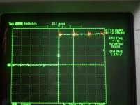
Here you can find measurement and the wave captured with the oscilloscope
Asynchronous I2S FIFO project, an ultimate weapon to fight the jitter
Here you can find measurement and the wave captured with the oscilloscope
Asynchronous I2S FIFO project, an ultimate weapon to fight the jitter
Yes, it's crosstalk between LRCK and BCK, the BCK clock is superimposed to the LRCK.
Although I don't know nothing about the schematic I presume that the crosstalk could come from the FPGA or from the output reclocker since has been used a single IC for all the signals to be reclocked.
Although I don't know nothing about the schematic I presume that the crosstalk could come from the FPGA or from the output reclocker since has been used a single IC for all the signals to be reclocked.
Couldn't this be the BCK from PLL side - how do you know it derives form the incoming side?
Another question, irrespectively where BCK originates from: how does it cause harm?
If user of LCRK uses positive edge triggering there should be no problem - edge looks really clean and sharp.
//
Another question, irrespectively where BCK originates from: how does it cause harm?
If user of LCRK uses positive edge triggering there should be no problem - edge looks really clean and sharp.
//
There is no PLL, Ian (as a good practice) does not use the PLL of the FPGA, the FIFO runs with fixed oscillators.
I don't know how the crosstalk could affect the performance, but as you have said the FIFO is source dependent.
As you have seen I have published the phase noise of the LRCK output, there is a bunch of noise floor and the close in phase noise is worse than the PN of the oscillator. As you know dividing down the phase noise should improve.
I cannot say more, I have no access to the hardware and to the firmware to evaluate the design.
OK - true - lets call it the "clean clock side". Just to be clear - I have read people say they hear differences on Ians fifo - I can't recall I have experienced this myself...
//
//
I have experienced myself replacing the oscillator of the source with a better one (not a state of the art clock) and the sound improved drastically.
And someone has reported similar difference about the DAM changing the source.
What does it means?
And someone has reported similar difference about the DAM changing the source.
What does it means?
- Home
- Vendor's Bazaar
- Reference DAC Module - Discrete R-2R Sign Magnitude 24 bit 384 KHz