Looking at the 1321 circuit board I see neither TP1 nor TP2.
Please, can you shed some light on this?
Thanks
Matt
Look closely, the two holes, larger than vias, at the end of the R-2R network (closest to the outputs).
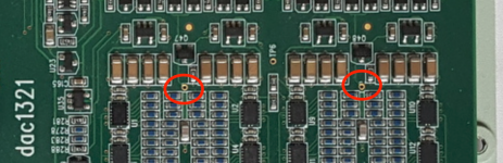
These? TP6=ground?
//
Yes, looks like the text has disappeared from the PCBs, and TP6 is GND.
Yes, looks like the text has disappeared from the PCBs, and TP6 is GND.
Thanks,
@soekris and @TNT
Matt
Intriguing... you dont happen to have an s/pdif inlet?
//
Here the picture from S/PDIF. The signal (fs=48kHz) comes from the optical out of a Mac Book Pro. The wandering signal is here in the 800Hz area.

I now have an idea what is going on. Hint by the observation that the level of the wandering peak does not increase when I increase the gain of the buffers of the ADC, I think what we are seeing is the clock of the DAM itself, aliased back in the audio band.
Then the peak (mean) frequency is explained by the slight difference of the clock frequencies of the ADC clock and the Amanereo clock, resp. the Mac Book clock in the S/PDIF case.
The ADC is 32x oversampling at 192kHz, so the aliases are in the passband of its digital low pass filter for +-96kHz + multiples of 6,144MHz. This fits well as the DAM clock should also be operating at some 2-power multiple of 48kHz.
As the input buffer of the ADC is not made for that high frequencies there is no effect of the gain setting - the signal gets trough only strongly attenuated.
So Soren is right - I need to push some wires around in my DAM 🙂
But first I would like to see the peak at its original frequency somehow.
Soren, could you please tell me at which nominal frequency the DAM clock is running with an fs=48kHz Input signal?
Last edited:
@soekris:
In a set-up WITHOUT headphones comparing dac1101 to dac1321:
Which one sounds better?
Thanks
Matt
In a set-up WITHOUT headphones comparing dac1101 to dac1321:
Which one sounds better?
Thanks
Matt
As the input buffer of the ADC is not made for that high frequencies there is no effect of the gain setting - the signal gets trough only strongly attenuated.
So Soren is right - I need to push some wires around in my DAM 🙂
But first I would like to see the peak at its original frequency somehow.
Soren, could you please tell me at which nominal frequency the DAM clock is running with an fs=48kHz Input signal?
44.1K / 48K * 1024 = 45.1584 Mhz / 49.152 Mhz Oscillator Clock.
@soekris:
In a set-up WITHOUT headphones comparing dac1101 to dac1321:
Which one sounds better?
Thanks
Matt
They use the same R-2R core, but in principle the dac1321 is a little more refined, like better power supplies and better output buffers, so the dac1321 will be a little better.
Yes, that is about what I paid last year. You can add a few more boards and it doesn't change the shipping any. This is one reason we have been bugging Soren about a US based store.
Yes, that is about what I paid last year. You can add a few more boards and it doesn't change the shipping any. This is one reason we have been bugging Soren about a US based store.
As it say on the soekris website "We are currently looking for additional online webshops to resell our products, primarily in USA and Asia, but also for other major markets."
Have talked to a couple, but haven't found the right one yet....
As it say on the soekris website "We are currently looking for additional online webshops to resell our products, primarily in USA and Asia, but also for other major markets."
Have talked to a couple, but haven't found the right one yet....
Is the diyAudioStore an option?
Soekris, I have been following this thread on and off, so please pardon me if this question was answered already.
As I understand it the FIFO on the input makes it pretty hazardous to use several boards simultaneously in an active crossover setup.
I think it was discussed early in the thread, but is there a way to synchronize several boards fed from AES3 signals with a common clock?
(let's say a miniDSP UDIO-8 for example)
Soekris, I have been following this thread on and off, so please pardon me if this question was answered already.
As I understand it the FIFO on the input makes it pretty hazardous to use several boards simultaneously in an active crossover setup.
I think it was discussed early in the thread, but is there a way to synchronize several boards fed from AES3 signals with a common clock?
(let's say a miniDSP UDIO-8 for example)
Don't know how you got that idea, it's not a problem, multiple dam1021 running on same clock will sync to within a few uS, multiple dam1121 can also be run synchronous.
Is the diyAudioStore an option?
Probably not, they need to carry the whole DAC range, and be able to participate at events....
How far away from each other may two 1121 be?
//
As far as you want, as long as the signals meet setup and hold times, which will limit how far they can be from each other....
DAM 1121: J3 14/16 (CLK) can they be connected by a twisted pair and boards configured as slave and master and J3 14/16 becomes input when slave and output when board is master?
Manual talks about Input Common mode Range and Output Swing...
Or must there be a third, external osc?
//
Manual talks about Input Common mode Range and Output Swing...
Or must there be a third, external osc?
//
Last edited:
So 6 meters should be OK?
What cables would you recommend?
//
Seems like I forgot to add setup and hold time to the manual, we're talking about 5 nS, so 6 meters will be kinda hard, but not impossible if you buffer the clock and signals and follow all high speed design rules....
In practice, when using the clock from the oscillator on one board feeding the other board, maybe 10 cm, when using an external oscillator feeding multiple boards, maybe 60 cm....
Multiple dam1121 are really supposed to be mounted next to each other.
- Home
- Vendor's Bazaar
- Reference DAC Module - Discrete R-2R Sign Magnitude 24 bit 384 KHz