One should avoid talking about technical aspects if he does not have the appropriate knowledge.
Exactly, now look in the mirror or alternatively read your posts in this topic.
As for my expertise, you've not yet presented anything that's worthy of discussion on technical merit so I have not weighed in with anything technical yet, you merely suggest I believe the subjective claims of others which also have no technical basis.
So I'm waiting for your technical analysis of the Soekris DAC's shortcomings/flaws and your proposed solution for these and a direct comparison with measurements showing that you've indeed tackled these shortcomings/flaws. Failing that don't expect anything technical from me, I don't speculate, I theorize, calculate, prototype, measure and THEN draw conclusions, I suggest you start doing the same.
You keep posting comments that are anything but technical.
Now it's clear, you have no idea how a FIFO works, you don't know what two time domains mean.
Just to confirm Lego Land rather than diy audio.
Just pretend that these subjective differences were confirmed with blind tests, then you wont need to keep side stepping the technical discussion of FIFOs.
Just pretend that these subjective differences were confirmed with blind tests, then you wont need to keep side stepping the technical discussion of FIFOs.
The curious thing is that these subjective differences have been reported from other members, not from me.
I have not yet powered on my DAM1021.
But people continues addressing to me about opinions published in this thread from other.
Maybe rather than a blind test it would take a "non-blind discussion"
Just pretend that these subjective differences were confirmed with blind tests, then you wont need to keep side stepping the technical discussion of FIFOs.
Just pretend? So besides opinion you now want to introduce make belief in this discussion, how exactly do you figure that would help the validity of andrea's claims?
Just pretend? So besides opinion you now want to introduce make belief in this discussion, how exactly do you figure that would help the validity of andrea's claims?
We all have understood you are an enthusiast follower who does not accept any criticism around the DAM.
But you should understand and accept (unless you demonstrate the contrary) that I have never claimed the DAM1021 is source dependent, simply because I have not yet got my DAM running.
Then if you does not agree with the members who have posted their impressions claiming the sound of the DAM is very different changing the source you should insult them rather than me, replying to their posts rather than mine.
Can you realize this?
I assume so.
Well, starting for the impressions reported from some members, since the designer dismissed the matter by saying that the DAM is almost perfect and there is no reasons he makes any change, I have tried to explain where this issue could come from.
Although I will measure the DAM1021 as I said several times, I have expressed my honest opinion supported by technical reasons: "using a FIFO buffer the DAC should not be affected by the source because they operate in differents time domains".
What is wrong in my technical explanation?
I'm here to learn so please explain what is wrong technically speaking.
But if you don't know the technical aspects please stop insult, spend your time to learn and finally post your comments.
I’m not sure why I keep expecting intelligent replies from you, replies that show technical competence, replies that show a good grasp of underlying technology and principles and last, but certainly not least, replies that show a thorough breakdown of the shortcomings/flaws on the Soekris DAC and how you aim to fix those. Failing those all you’re doing is portraying yourself as a charlatan, unable to move beyond unsubstantiated claims, making yourself look less credible with every request for more information. I’m not the one that needs to prove anything here, you are, as you are the one making unsubstantiated claims.
I’m not sure why I keep expecting intelligent replies from you, replies that show technical competence, replies that show a good grasp of underlying technology and principles and last, but certainly not least, replies that show a thorough breakdown of the shortcomings/flaws on the Soekris DAC and how you aim to fix those. Failing those all you’re doing is portraying yourself as a charlatan, unable to move beyond unsubstantiated claims, making yourself look less credible with every request for more information. I’m not the one that needs to prove anything here, you are, as you are the one making unsubstantiated claims.
Why you continue ignoring that the claims you are referring are not mine?
For your knowledge I have already explained how I aim to fix the issue, from the technical point of view posting even the schematic and the board layout
Implementing a true FIFO buffer with low phase noise clock on the Soekris DAM1021 DAC
I'm not sure you have the skills to understand the schematic.
Last edited:
I'm not sure you have the skills to understand the schematic.
You've taken a few logic gates from the library in Altium and put those on a schematic sheet, applause, what an heroic effort 😀
Why so hostile? Even though this is a vendor site, we are here on diyaudio.com where you can assume some basic interest in technical things.
I find the Soekris DAC very interesting for many technical reasons. I think the Soekris concept is basically brilliant. The technical issue here is very fundamentally about implementing FIFOs. Better said the question if a complete isolation of this FIFO is possible. This is certainly not only related to Soekris a very interesting question. It also concerns Ian's work, among others. But it has just become an issue here.
In this respect I like to follow this thread regarding the very few(!) technical thoughts that are thrown in here. Besides Andrea's approach i.e. also Markw4's input (i.e. #9559) and the open question of "living sound". I don't understand why people don't even want to know how (if?) the problem is solvable...? The solution may have striking effects on how to build DACs in the future. Or does anyone think there is a device in the world that can't be made better?
Soeren sorry to dig up this old topic but you said that for the dam1121 the si570 with total stability of 20ppm (BC***112DG) cannot be used and it’s obvious, as the config registers differ from the si570 with 61.5ppm (BA***112DG) and 31.5ppm (BB***112DG).
That would leave me with the conclusion, that the BB***112DG with 31.5ppm total stability can be used. Can you confirm this?
Thanks
That would leave me with the conclusion, that the BB***112DG with 31.5ppm total stability can be used. Can you confirm this?
Thanks
Why so hostile? Even though this is a vendor site, we are here on diyaudio.com where you can assume some basic interest in technical things.
I find the Soekris DAC very interesting for many technical reasons. I think the Soekris concept is basically brilliant. The technical issue here is very fundamentally about implementing FIFOs. Better said the question if a complete isolation of this FIFO is possible. This is certainly not only related to Soekris a very interesting question. It also concerns Ian's work, among others. But it has just become an issue here.
In this respect I like to follow this thread regarding the very few(!) technical thoughts that are thrown in here. Besides Andrea's approach i.e. also Markw4's input (i.e. #9559) and the open question of "living sound". I don't understand why people don't even want to know how (if?) the problem is solvable...? The solution may have striking effects on how to build DACs in the future. Or does anyone think there is a device in the world that can't be made better?
You have got the point.
You are here (like me) to exchange opinions and impressions about the topic of this forum: diy audio.
And like me you are here to debate technical questions around diy devices, because audio means electronic and electronic needs technical approach.
Mostly we are here to learn and experiment in the spirit of a DIY audio forum.
But when someone does not have the slightest electronic knowledge, is unwilling to learn and pretends to discuss technical topics then he becomes aggressive and the only word he has at his disposal is the insult.
I'm not worried about that, fortunately most of the members of this forum have our approach and only a few people are like someone who keeps insulting without adding anything constructive to the discussion.
I’m starting to think you are delusional as well Andrea? I’m not the one making bold and unsubstantiated claims in someone else’s topic, speculating about shortcomings and flaws in its design yet never offering anything factual or with a solid technical explanation. It is laughable Andrea, truly laughable and has absolutely nothing to do with the spirit of a DIY audio forum.
I finally did some measurements in context of the frequency adjustment of the FIFO of the DAM 1021.
The measurements were made one after the other. So if there are multiple plots in one picture, a bump at a certain time in one has no correspondence to the event at the "same time" in the other plots.
Lets start with a measurement of the DAM FPGA master clock output (this is the frequency of its SI514 oscillator divided by 2).
The blue plot is the measurement with a signal at 44100 kHz sample rate feeding the DAM, thus the DAM here is doing frequency adjustments. The pink plot is the measurement when the DAM is not locked to a source. In this case the its clock just keeps running with the last frequency, thus here we have a measurement of the clock where the DAM is doing NO frequency adjustments. Second picture the same zoomed in somewhere in the "middle".
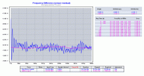
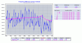
The plots show the residual of the measurements from the line fitted to the measurement points. Loosely speaking we see the deviation after removing offset and (linear) drift (the numbers of these are given in the tables on the right).
We see several things:
The big oscillation at the beginning of the blue plot is caused by the removal of the frequency offset. The adjustment approaches the aimed value in an oscillation (over and undershoot) and needs about 3 oscillations of a period of about 100 seconds each to "do its job".
The adjusted clock never reaches the "stability" of the unadjusted clock, we see that there are all over more or less strong "100s-oscillations" thus "slight" adjustments all over the time with this over-undershoot behaviour.
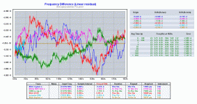
The next plots are to illustrate that this issue is not really caused by instability of the signal fed to the DAM. The DAM is fed by an I2S signal. We measure again the DAM FPGA master clock. Again the blue plot is for the I2S signal clocked by a Crystek CCHD-957 (stability plots of several clocks are shown later). The green plot is for the I2S signal clocked by a signal generator which is much more stable - surely stable beyond the measurement capabilities of the DAM.
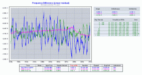
While we see a slight improvement, the situation is essentially the same. Although the input is "perfect" for the green plot, the DAM measures with its own clock as reference and thus must do adjustments to compenstae the drift and frequency noise of its SI514 (pink).
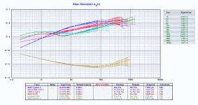
Perhaps more informative is the plot of the Allan deviations.
The blue plot is the DAM master clock with the Cryteck input.
The green plot is the DAM master clock with the generator input.
The pink plot is the unadjusted SI514.
The red plot is the signal generator.
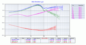
We see that the DAM master clock plots look alike up to 100 seconds. After 100 seconds the plot with the generator input starts to follow the generator itself due the PLL. While the Crystek plot follows the Crystek - which behaves essentially like the SI514. We also see that below 100s the DAM master clock plots are worse than the SI514-plot.
Next I make jumps of different magnitude in I2S clock frequency (of 22.22400MHz). The DAM measures the I2S-bit-clock which is running at 1/8 of that.
At t~0 a jump of +10Hz (so ~0.5ppm)
at t~700 a jump of -5Hz
at t~1900 a jump of -2.5Hz
at t~2700 a jump of -1Hz
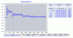
We see that the magnitude of the oscillation is correlated to the magnitude of the jump in the I2S signal. The -1Hz jump vanishes in the noise.
Audible or not, I thing that shows there is room for improvement with the DAM PLL.
Ideally the DAM master clock plot should look like the SI514 below "100 seconds" (the PLL filter bandwidth?) and then approach the performance of the clock of the input.
To conclude stability plots of several clocks, a Crystek CCHD-957 (blue), a NDK NZ3225SDA (pink), a SI514 (green), a SI570 (red), a cheap no name (light blue), signal generator (brown).
Although the clocks have individual shapes, in a big picture approach all the clocks perform, in terms of stability, more or less alike.
The measurements were made one after the other. So if there are multiple plots in one picture, a bump at a certain time in one has no correspondence to the event at the "same time" in the other plots.
Lets start with a measurement of the DAM FPGA master clock output (this is the frequency of its SI514 oscillator divided by 2).
The blue plot is the measurement with a signal at 44100 kHz sample rate feeding the DAM, thus the DAM here is doing frequency adjustments. The pink plot is the measurement when the DAM is not locked to a source. In this case the its clock just keeps running with the last frequency, thus here we have a measurement of the clock where the DAM is doing NO frequency adjustments. Second picture the same zoomed in somewhere in the "middle".


The plots show the residual of the measurements from the line fitted to the measurement points. Loosely speaking we see the deviation after removing offset and (linear) drift (the numbers of these are given in the tables on the right).
We see several things:
The big oscillation at the beginning of the blue plot is caused by the removal of the frequency offset. The adjustment approaches the aimed value in an oscillation (over and undershoot) and needs about 3 oscillations of a period of about 100 seconds each to "do its job".
The adjusted clock never reaches the "stability" of the unadjusted clock, we see that there are all over more or less strong "100s-oscillations" thus "slight" adjustments all over the time with this over-undershoot behaviour.
The next plots are to illustrate that this issue is not really caused by instability of the signal fed to the DAM. The DAM is fed by an I2S signal. We measure again the DAM FPGA master clock. Again the blue plot is for the I2S signal clocked by a Crystek CCHD-957 (stability plots of several clocks are shown later). The green plot is for the I2S signal clocked by a signal generator which is much more stable - surely stable beyond the measurement capabilities of the DAM.

While we see a slight improvement, the situation is essentially the same. Although the input is "perfect" for the green plot, the DAM measures with its own clock as reference and thus must do adjustments to compenstae the drift and frequency noise of its SI514 (pink).
Perhaps more informative is the plot of the Allan deviations.
The blue plot is the DAM master clock with the Cryteck input.
The green plot is the DAM master clock with the generator input.
The pink plot is the unadjusted SI514.
The red plot is the signal generator.

We see that the DAM master clock plots look alike up to 100 seconds. After 100 seconds the plot with the generator input starts to follow the generator itself due the PLL. While the Crystek plot follows the Crystek - which behaves essentially like the SI514. We also see that below 100s the DAM master clock plots are worse than the SI514-plot.
Next I make jumps of different magnitude in I2S clock frequency (of 22.22400MHz). The DAM measures the I2S-bit-clock which is running at 1/8 of that.
At t~0 a jump of +10Hz (so ~0.5ppm)
at t~700 a jump of -5Hz
at t~1900 a jump of -2.5Hz
at t~2700 a jump of -1Hz

We see that the magnitude of the oscillation is correlated to the magnitude of the jump in the I2S signal. The -1Hz jump vanishes in the noise.
Audible or not, I thing that shows there is room for improvement with the DAM PLL.
Ideally the DAM master clock plot should look like the SI514 below "100 seconds" (the PLL filter bandwidth?) and then approach the performance of the clock of the input.
To conclude stability plots of several clocks, a Crystek CCHD-957 (blue), a NDK NZ3225SDA (pink), a SI514 (green), a SI570 (red), a cheap no name (light blue), signal generator (brown).
Although the clocks have individual shapes, in a big picture approach all the clocks perform, in terms of stability, more or less alike.


OK - some questions for clarity.
- Not one single trace is from the same period of time - not within chart or between?
- By "first 100 sec" - is this just after a lock or maybe power on?
- I suppose a "new 100 sec" would occur after; power on, ->lock, Fs change - more?
- What is your external frequency ref? Did you try to listen to using this on the Amanero?
So all of this is about frequency stability and not jitter - just to clear that out. Jitter is yet 1000 times smaller aberrations. So why is it interesting - well, for user 'living sounds' its might be the cause for a multi DAC sync issue. All these frequency adjustements of the Si may have a negative effect on SQ - some reports say USB sounding better on DAMs with built in USB where when used, clock adjustment don't take place acc to Sören.
The frequency alteration themselves are hardly noticeable as they are in the region of mHz. Only Furthwängler would catch that 😉
//
Every measurement is from a different period of time. I have only one single channel frequency counter. However some different plots are from the same measurement. For one you can do the frequency deviation, zoom of that, Allan variance, all from the same stored measurement. Moreover the same measurement, e.g. the free running SI5i4, appears in different charts.OK - some questions for clarity.
- Not one single trace is from the same period of time - not within chart or between?
No all measurement were made after everything was powered up for at least an hour. After power on the clocks drift like hell. A lock/unlock was made by starting/stoping to play a music signal.- By "first 100 sec" - is this just after a lock or maybe power on?
- I suppose a "new 100 sec" would occur after; power on, ->lock, Fs change - more?
The heavy oscillation in the beginning of the plot (if that is what you mean by first/new 100sec) is due compensating the offset. The offset arrised by either measuring a other clock than in the previous measurement or by a long delay between the measurements due to drift. As sample rate change would have an comparable effect.
The "first 100 sec" in the Allan variance plot have a very different meaning:
Allan variance - Wikipedia
A "slightly" dated signal generator of one of the big brands in measurement equipment 🙂- What is your external frequency ref? Did you try to listen to using this on the Amanero?
No I did not listen music with it - the thing has loud fans. Moreover as typical "boat anchor" it weights over 20kg and I do not want to carry it around the house.
Yes. I thing frequency stability is what affects the frequency adjustments of the DAM. The DAM frequency measurements take their time. Jitter affects the sound due to other "channels" than by effects on the frequency adjustments, I would say.So all of this is about frequency stability and not jitter - just to clear that out.
Jitter is yet 1000 times smaller aberrations. So why is it interesting - well, for user 'living sounds' its might be the cause for a multi DAC sync issue. All these frequency adjustements of the Si may have a negative effect on SQ - some reports say USB sounding better on DAMs with built in USB where when used, clock adjustment don't take place acc to Sören.
The frequency alteration themselves are hardly noticeable as they are in the region of mHz. Only Furthwängler would catch that 😉
//
Yes the mHz changes in music is most likely no issue by itself. But as e.g. my recording of a square wave (in some earlier post) showed it has well measurable effects. Probably 'living sounds' knows better what can happen.
- Home
- Vendor's Bazaar
- Reference DAC Module - Discrete R-2R Sign Magnitude 24 bit 384 KHz