Careful with connecting all pins, some may be unique to each board and need to be unconnected/removed. Like the serial/FPGA/MCLK outputs.
Isolated serial will be voltage divided by a 1K if with Audiozen SK Lite.
Got it, thanks! I'll try to find some long pin headers and use only the pins necessary
I'm buying it from a reputable vendor on Taobao, and I think you should give more credits to these Taobao replicas - some use very high precision oscillators. Not sure about firmware though... The main thing is that I believe there will be no difference in SQ as long as the isolation chip is powered right, let me know if that assumption is dubious and I'll go straight back to C1 with separate 5v supply...
It's not a matter of reputation of the vendor. If the Amanero clone costs $20, you can be sure that the oscillators are cheap. If its cost were > $30, it would be a different thing.
Regarding the firmware, Amanero has put in place server-side protection for such cases. If you are considering purchasing one of these boards, you should ask the seller if you can update the board's firmware with Amanero's tool.
Regarding differences in SQ, the main factor is the oscillators, a secondary factor is the LDOs.
But we are getting way off topic.
You're probably right about the firmware, the seller just said it's running the latest version. The oscillator doesn't look the best, (here's the link if you want to check it out lol ??? I2S???Amanero usb iis???? DSD ??384K DSD512-???) but like I said, I believe that as long as the output is not total crap, FIFO should be able to handle it.
Then again I'm not an EE person so I could very well be completely mistaken about how the isolation and FIFO works on the dam1021. If the output jitter of the USB board does make a difference, please let us know..
Good crystals are expensive, so don't expect miracles for $20. And also, fifo reclocking can help, but IMHO its not a cure all. To some extent, garbage in, garbage out. You can't fix it all with fifo.
For your build, I'd consider making a sort of breadboard with one 1021 first. It would be a pain to troubleshoot the lower 1021 in a stacked arrangement, if the lower one doesn't work. So before spending a lot of time getting the wiring perfect, just get things connected reasonably, and see if you get sound. But my build is still in a breadboard state after years lol. Getting a project cased to look nice takes a lot of time.
Randy
Given that the clock behind the fifo is better than the incoming, fifo should help with timing/jitter issues. Information loss of course not.
If incoming clock is really bad and you have a short fifo like in the DAM there could be issues - but its not that short so it's really strange that people reports change in sound when chancing timing aspects upstream. Either they are delusional or there is someting wrong with the DAM implementation. Worst case is that it should sound perfect for 30 seconds batches with some glitch in between.. (?)
//
Good crystals are expensive, so don't expect miracles for $20. And also, fifo reclocking can help, but IMHO its not a cure all. To some extent, garbage in, garbage out. You can't fix it all with fifo.
For your build, I'd consider making a sort of breadboard with one 1021 first. It would be a pain to troubleshoot the lower 1021 in a stacked arrangement, if the lower one doesn't work. So before spending a lot of time getting the wiring perfect, just get things connected reasonably, and see if you get sound. But my build is still in a breadboard state after years lol. Getting a project cased to look nice takes a lot of time.
Randy
I wired up everything on paper (ikr...) but you're right about working with just one board first. It seems to me the challenge is more in the mechanical mounting than wiring, since I'm fitting everything in 215*228*70..
Given that the clock behind the fifo is better than the incoming, fifo should help with timing/jitter issues. Information loss of course not.
If incoming clock is really bad and you have a short fifo like in the DAM there could be issues - but its not that short so it's really strange that people reports change in sound when chancing timing aspects upstream. Either they are delusional or there is someting wrong with the DAM implementation. Worst case is that it should sound perfect for 30 seconds batches with some glitch in between.. (?)
//
My belief is that their perceived change in SQ is due to the power source quality. C-1 has better LDO and overall regulation than Amanero. If you use the 3.3V from the USB receiver, there should be a difference. I asked Singxer and he also thought that if you have FIFO reclocking, the incoming jitter doesn't matter all that much, but the power might. I think somewhere Soren also said he was sure that incoming jitter won't matter.
Board Mods?
Hey Spikestabber,
I gathered all the parts for my build, but I'm still unsure about one thing. What mods on the dam1021 are known to be effective? I know that there's the vref caps (4 for each board), and maybe the 3.3v regulator? I remember someone did tests on different caps but couldn't remember if there was ever a verdict. It would be great if you could just briefly summarize what you did (lots of mods in your latest build photo..) so we could perhaps follow.
Thank you!
I have very much the same configuration you are asking about, the SK-Lite integrates well with dual-mono. I've also used the same linear 3.3v source from the sk-lite for the dam1021 isolation along with the 5V for the USB to I2S.
Hey Spikestabber,
I gathered all the parts for my build, but I'm still unsure about one thing. What mods on the dam1021 are known to be effective? I know that there's the vref caps (4 for each board), and maybe the 3.3v regulator? I remember someone did tests on different caps but couldn't remember if there was ever a verdict. It would be great if you could just briefly summarize what you did (lots of mods in your latest build photo..) so we could perhaps follow.
Thank you!
The vref mods aren't really needed if you have a newer than v2 board, but its very easy to add new caps to the newer boards so its an easy upgrade if you must do one upgrade. My boards are v2 so I did the super regulator transistor follower which keeps the vref feedback loop completely intact while eliminating the series resistors.
The vref supply impedance is as close to 0R as you're going to get. I don't recommend using the stock AC supply if anyone chooses that route, the boards should already have super clean bipolar DC supply. I've also bypassed the onboard bridge rectifier as a result.
The other mods that might improve newer boards are upgrading the 3.3V supply. Near the clock I added extra 1uF/10uF stack of smd caps and a larger 1400uF one on the headers near the clock. I also put offboard discrete Sparko 3.3V regulators in place of the onboard LDO's.
I found the stock LDO's to run very warm with the +/-15VDC supply and made the clock pretty hot as well due to the close proximity to the LDO. It was warmer for the bottom board due to the enclosed space. As for SQ improvements? Of course its arguable, I do know that the 3.3V rail now has immeasurable noise according to my scope.
If you don't use an add-on headphone amplifier board or the onboard buffers you won't need the higher DC voltages, you can run the setup all the way down to +/-7VDC if you only plan on using raw outputs which makes the stock LDO considerably cooler.
Another way around this would be to use more supply rails, however I wanted this to be a rather compact design in which I very much succeeded.
Last edited:
Just so everybody know, we're running a Christmas Special Pricing on the dam1021-12: EUR 245 each, valid until December 31, 2017.
We also have Christmas Special Pricing on some of the dac1xxx products....
We also have Christmas Special Pricing on some of the dac1xxx products....
Hi,
as of 12th of December
dac1321 order this year 460 € later 490 €
dac1421 order this year 765 € later 850 €
dac1541 order this year 1150 € later 1290 €
last time I had a look (before the 12th of december)
dac1321 460 €
dac1421 735 €
dac1541 1290 €
All prices exculding VAT
Merry Christmas
as of 12th of December
dac1321 order this year 460 € later 490 €
dac1421 order this year 765 € later 850 €
dac1541 order this year 1150 € later 1290 €
last time I had a look (before the 12th of december)
dac1321 460 €
dac1421 735 €
dac1541 1290 €
All prices exculding VAT
Merry Christmas
Just so everybody know, we're running a Christmas Special Pricing on the dam1021-12: EUR 245 each, valid until December 31, 2017.
We also have Christmas Special Pricing on some of the dac1xxx products....
Am I the only one that bought the 1541 at 1290EUR + VAT?
Anyway, the DAC is great at the price I bought it, and it is a steal at 11% less.
Roberto
I like DSD too, so I designed this DoP to native DSD solution for RPi. It should be no problem working with DAM1021 that has DSD support. Just hope I get chance to try.
DopDecoderIsolator1 by Ian, on Flickr
Ian
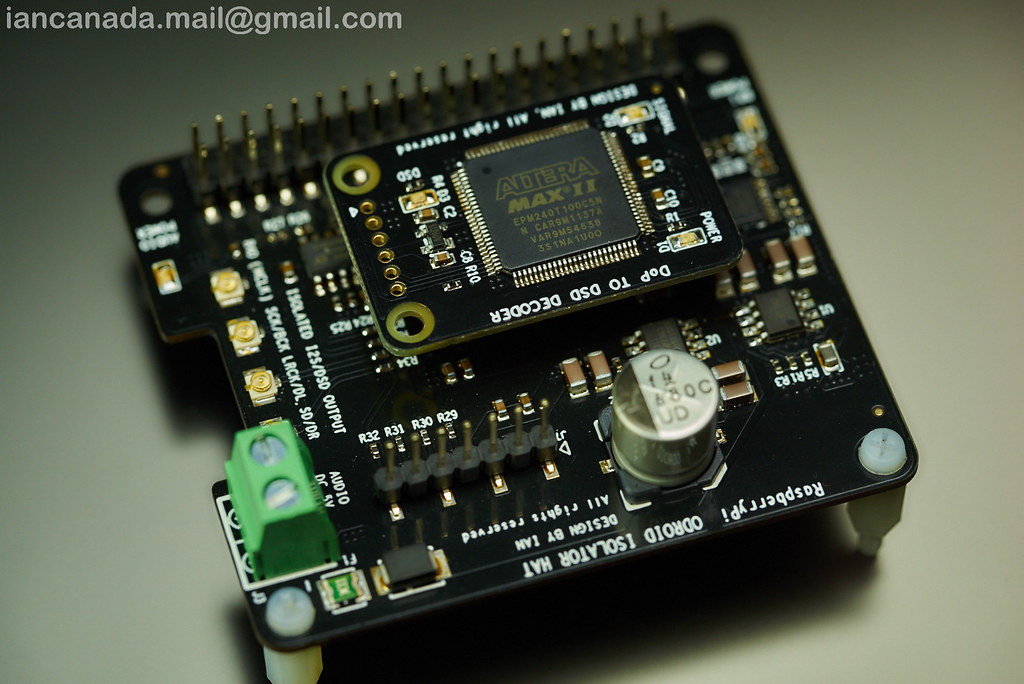
hey ian i just got your pi isolator board and the daughter DoP decoder board everything works but with latest volumio version i dont get the dsd led on also the i2s led flashes when i try dsd playback and the sound stutters no matter if i choose native dsd or DoP hmmm.
sound with the isolator and high res files is great 🙂
cheers janosch
got it sorted thx to dimdim 🙂 problem was that i had in volumio audio resampling on cause dam1021 otherwise dont play 16bit stuff but now the dsd lamp on the daughter board is on and it sounds wunderfull 🙂 me happpy 🙂))
cheers janosch
cheers janosch
The vref mods aren't really needed if you have a newer than v2 board, but its very easy to add new caps to the newer boards so its an easy upgrade if you must do one upgrade.
The vref supply impedance is as close to 0R as you're going to get.
So if I understood this correctly, adding caps to v4 has only very limited effect?
My boards are v2 so I did the super regulator transistor follower which keeps the vref feedback loop completely intact while eliminating the series resistors.
Honestly I don't know what this means... will keep it at the back of my mind if I do get around to writing something..
I don't recommend using the stock AC supply if anyone chooses that route, the boards should already have super clean bipolar DC supply.
I'll be using an s22 at 9V DC if that's good enough...
I've also bypassed the onboard bridge rectifier as a result.
did you manually bypass the bridge rectifier? Would you recommend this mod?
The other mods that might improve newer boards are upgrading the 3.3V supply. Near the clock I added extra 1uF/10uF stack of smd caps and a larger 1400uF one on the headers near the clock. I also put offboard discrete Sparko 3.3V regulators in place of the onboard LDO's.
I found the stock LDO's to run very warm with the +/-15VDC supply and made the clock pretty hot as well due to the close proximity to the LDO. It was warmer for the bottom board due to the enclosed space. As for SQ improvements? Of course its arguable, I do know that the 3.3V rail now has immeasurable noise according to my scope.
Do you know what the 3.3v rail is used for besides SPDIF inputs? I'll check the temps once my transformer arrives, but I do have a bit more room in the chassis to fix the regulators to.
Also, just found out Sparko is $47 a piece! Is the NewClassD used by jacklee of similar quality? Where else might one look for a quality discrete regulator?.. Thanks!
If you don't use an add-on headphone amplifier board or the onboard buffers you won't need the higher DC voltages, you can run the setup all the way down to +/-7VDC if you only plan on using raw outputs which makes the stock LDO considerably cooler.
Would it be a problem if I use +/-9V DC with the buffers? I'll be mainly using hd650 directly with it I think.. I've not actually heard this before so any explanation would be helpful to a noob!
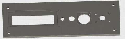
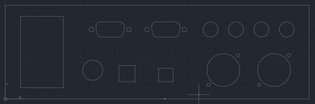
Also, would you happen to know the hole dimensions on the SK Lite encoder board? I measured 24*16, and Audiozen has not responded to my questions... I'm almost done with the front&back panel for the 215*228*70 dual mono 1021 enclosure. Here's a preview 🙂
Hopefully the case will turn out nice.. as will the sound of the setup. I'll keep you guys updated!
Attachments

Sounds like your setup is a good candidate for dual-mono. I run raw outputs straight to headphone buffer and amplifier, no longer using the onboard buffers.

Finally ordered my enclosure but realized that to really do everything decently well in a box for hd650 there may be additional buffering required...
My goal is to drive hd650 well from an electrical standpoint, not worrying about subjective SQ for now. Would the onboard opamps suffice in a dual-mono setup or is there additional buffering/amplification required? I read somewhere that to get to the theoretical 120dB SPL of the headphone the peak power should be 12V / 40mA...
Thanks so much!
@Soren
If the first step of filtering/signal processing is done by the computer, it would be nice to have the following features in a future firmware. Would this make too much trouble?
1.) For 352.8, 384 Ksps an (optional) real bypass of FIR1.
I.e. that the bits sent will be the input of FIR2 (if the volume is set to 0dB). Currently this is not the case due to the multiplicator (that can not be set 1) and possibly due to the DC blocking filter and the De-emphasis.
2.) That 32-bit input signals are not truncated to 24 bits.
If necessary, for some reason, this feature would be sufficient only for the real-FIR1-bypass.
I know the low order bits should make no difference for listening but there is no possibility to make experiments in that direction now. Moreover the filter coefficients are also of higher precision for some reason 😉 .
P.S.
there is a third thing that would be nice if it would be "fixed" with a new firmware.
The DAM truncates and not rounds numbers. This can lead to issues that would not happen with rounding.
An example: DC filter and de-emphasis off. FIR1 bypass with multiplicator 2^{-24}(2^{24}-1) and FIR2 bypass with multiplicator 2^{-24}(2^{24}+1).
Then with input signal 1/2 the MSB of the positive ladder will be active -> OK.
With input signal -1/2 all but the MSB of the negative ladder will be active -> 🙁 .
At least if you need to control exactly the active bits on the ladder (e.g. if you want to investigate the errors due to the resistor errors) this leads to extra work and is error prone.
@Soren
If the first step of filtering/signal processing is done by the computer, it would be nice to have the following features in a future firmware. Would this make too much trouble?
1.) For 352.8, 384 Ksps an (optional) real bypass of FIR1.
I.e. that the bits sent will be the input of FIR2 (if the volume is set to 0dB). Currently this is not the case due to the multiplicator (that can not be set 1) and possibly due to the DC blocking filter and the De-emphasis.
2.) That 32-bit input signals are not truncated to 24 bits.
If necessary, for some reason, this feature would be sufficient only for the real-FIR1-bypass.
I know the low order bits should make no difference for listening but there is no possibility to make experiments in that direction now. Moreover the filter coefficients are also of higher precision for some reason 😉 .
Can't see the problems, all dam1021 internal processing are done with 35 bit, the filters have 66 bits results, the coefficients are 32 bits, the internal signal are then finally reduced to 28 bits and output to the R-2R networks, don't even remember if I truncate or round as it is so unimportant with 28 bits.... So it's not a priority to improve on....
Can't see the problems, all dam1021 internal processing are done with 35 bit, the filters have 66 bits results, the coefficients are 32 bits, the internal signal are then finally reduced to 28 bits and output to the R-2R networks, don't even remember if I truncate or round as it is so unimportant with 28 bits.... So it's not a priority to improve on....
I know, I know 🙂 🙂
You truncate, I tested it.
As my example shows, truncate and round make a difference as the negative of a signal is not always mapped to the same state of the DAC ladder (ladders swapped) as the positive signal. (A serious lack of symmetry 😉 )
Yes, the difference is at most the magnitude of the last bit. I agree that for listening this is probably not of importance.
But you miss the marketing terms "bit perfect" and "32-bit input". 😀
OK but getting serious again, the missing features make it harder to put the DAM-ladder, with all of it bits, in a predefined state without fiddling around with several filters and tweaked signals.
- Home
- Vendor's Bazaar
- Reference DAC Module - Discrete R-2R Sign Magnitude 24 bit 384 KHz