comicketkit,
Nigel found that 3.3 volts was plenty for vRef and the others who have done this have had the same good experience. Two of those batteries in series for 4 or so volts will make for unhappy batteries, I would fear.
My output is plenty strong - and is driving multiple amplifiers.
The ground idea, I am sorry I missed that, sounds worth trying but I left the board's grounding as is. Hadn't even thought about that!
I do have the input and output grounds assisted by wire which is attached to a single point at the input side of the board since that is where SOEKRIS said was the best place to access ground - removing those reservoir caps and you have a nice pad to work with.
comicketkit,
Nigel found that 3.3 volts was plenty for vRef and the others who have done this have had the same good experience. Two of those batteries in series for 4 or so volts will make for unhappy batteries, I would fear.
My output is plenty strong - and is driving multiple amplifiers.
The ground idea, I am sorry I missed that, sounds worth trying but I left the board's grounding as is. Hadn't even thought about that!
I do have the input and output grounds assisted by wire which is attached to a single point at the input side of the board since that is where SOEKRIS said was the best place to access ground - removing those reservoir caps and you have a nice pad to work with.
Hi Rick,
Thanks so much, you reminded me to ground on single point should be a better idea.
While enjoying music and the batteries power is running down (sure, it keeps on 3.3v supply on long period), I am often worrying there is a voltage different supplied to vref. As mentioned by Soekris, the second harmonic will be drop down in this case.
Therefore, my idea is to using low noise regulators (TPS7a4700) to step down battery voltage from 6.6vdc to 3.8vdc. Two batteries in series power up (+3.80)vref and other two in series power up (-3.80)vref. It keeps the same voltage supply to 2 decimals in longer period.
But I am just curious, will the regulator injects noise or lowers output impedance and then worse the performance of batteries mod.
First I use three boards:
1. The board from Kiven Chen (see this thread). With this board you can piggyback the dam1021.Additionally there is a connector for the USB-Amanero. I use this connector for my little receiver board which is build around the SRC4192.
H
2. Receiver board: This board converts with a high precision clock and the SRC4192 the 24 Bit 44,1 KHz I2S signal from my CD-Pro-2 to 32 Bit 48 KHz I2S. You need this conversion for the dam1021, which only can operate 32 Bit I2S.
I´ve built this board similar to the TPA Metronome, but with fixed configuration.
3. Control board: This board is the base of my Teensy 3.2. I control with the Teensy the following functions:
a) CD-PRO 2: power supply
b) CD-PRO 2: DSA-interface
c) Infrared RC
d) SD-Card to change filter files
e) Via RX/TX control the dam1021
f) OLED display
g) 4 keys to control the CD-Player directly without RC
The code is written in Arduino C.
This board is also made by myself.
The case is from Modushop Italy
My project is not only a CD-Player, but also a DAC for external sources. One for SPDIF and one for Toslink. I've also implemented a routine to change the filter files with the ir-remote. The filters, you can use, are on a SD-card on the back of the player.
The CD-Pro 2 in this configuration sounds perfect. The combination with the dam1021 and I2S CD-Pro 2 is far superior to a connection with SPDIF!
I hear mainly classical music and I love this cd-player. The sound is really astonishing! I own a really great CD-Transporter CEC-5N. This very professional player has no chance against my home built cd player.
This is a very impressive project. I am building something similar (conceptually) but based on Kenwood DP X9010 transport.
Regarding Philips i2s specification, which reportedly is used for the dam1021:
3.1 Serial Data
Serial data is transmitted in two's complement with the MSB first. The MSB is transmitted first because the transmitter and receiver may have different word lengths. It isn't necessary for the transmitter to know how many bits the receiver can handle, nor does the receiver need to know how many bits are being transmitted. When the system word length is greater than the transmitter word length, the word is truncated (least significant data bits are set to `0') for data transmission. If the receiver is sent more bits than its word length, the bits after the LSB are ignored. On the other hand, if the receiver is sent fewer bits than its word length, the missing bits are set to zero internally. And so, the MSB has a fixed position, whereas the position of the LSB depends on the word length. The transmitter always sends the MSB of the next word one clock period after the WS changes. Serial data sent by the transmitter may be synchronized with either the trailing (HIGH-to-LOW) or the leading (LOW-to-HIGH) edge of the clock signal. However, the serial data must be latched into the receiver on the leading edge of the serial clock signal, and so there are some restrictions when transmitting data that is synchronized with the leading edge (see Figure 2 and Table 1).
So, if the 24 bit i2s output from a Philips made cd pro 2 drive is not compatible with the i2s input of dam1021, then something is differently programmed in dam1021 and does not meet the true Philips i2s specification. Can dam1021 FPGA be programmed to accept 24 bit word length?
Last edited:
Hi Rick,
Thanks so much, you reminded me to ground on single point should be a better idea.
While enjoying music and the batteries power is running down (sure, it keeps on 3.3v supply on long period), I am often worrying there is a voltage different supplied to vref. As mentioned by Soekris, the second harmonic will be drop down in this case.
Therefore, my idea is to using low noise regulators (TPS7a4700) to step down battery voltage from 6.6vdc to 3.8vdc. Two batteries in series power up (+3.80)vref and other two in series power up (-3.80)vref. It keeps the same voltage supply to 2 decimals in longer period.
But I am just curious, will the regulator injects noise and really lowers output impedance and then really worsens the performance of batteries mod.
Not sure what nige2000 intended with that last post but I can speak for what we are both doing; I am doing what nige2000 is doing with his setup AND THAT IS keeping the regulator connected at all times!
I defy you to hear additional noise. Plus, I have found, the batteries start depleting fairly quickly without their "chargers" so it would be impossible to maintain a constant voltage for vRef.
nige2000 has been working with the "powered battery" concept for much longer than I and when he tells me he can hear no difference between the regulator attached and not, I believe him. He is not lacking in audio obsessiveness so if the regulator harmed the sound he would not have adapted this technique to just about everything he uses for listening to music.
Just give it a try. Ignore all of those who say it is "wrong". I bet they have never tried anything like this. They enjoy sharing their considerable opinions as opposed to considered opinions.
Keeping it simple is the key. Good audio loves simplicity. AS simple as can be without being too simple, of course.
Maybe there is a better way but I sincerely doubt it.
You and I are using the same reg for the vRef batteries. If you can hear that regulator while it is keeping those batteries charged you have a hearing acuity that must HURT! Just painful to live with!!!
Just give it a try for a week with one battery charged to 3.3 volts for each resistor stack, minding polarities, of course, (four total) and I bet you will not find a need to mess with it any longer.
Take care,
I'm using I2S from a sd card player and just realized the soekris has been playing even though I forgot to turn on the 3.3v isolated power. I thought it was necessary?
It's supposed to be necessaryI'm using I2S from a sd card player and just realized the soekris has been playing even though I forgot to turn on the 3.3v isolated power. I thought it was necessary?
But i think this phenomenon was mentioned before
In this thread
It has been mentioned a number of times. For low SRs you can get the isolators to pass enough signal to get a lock even without power on the dirty side. But as SRs go up it becomes necessary to properly power the isolators. But even for 44.1K SR I wouldn't skip powering the isolators. I'm pretty sure that signal integrity suffers with no power.
It has been mentioned a number of times. For low SRs you can get the isolators to pass enough signal to get a lock even without power on the dirty side. But as SRs go up it becomes necessary to properly power the isolators. But even for 44.1K SR I wouldn't skip powering the isolators. I'm pretty sure that signal integrity suffers with no power.
SR?
I bet that is SAMPLE RATE.
Another anomaly I have found due to the fact that my output and input sections are powered separately and have separate power switches is that with the power to the resistor stacks off (and the input on, of course) there is still sound coming from the dac. Not much but it is easily heard and seems to be clean though missing the lower octaves. Kind of an AM radio tonal balance.
I accidentally discovered this and thought "WHAT HAVE I DOWN NOW?" until I noticed the switch was in the off position.
Nonetheless, I would not have thought it would make any sound at all.
I have also discovered, that contrary to some discussions on this thread, after I have removed opamps supplying 4V vref, all SE and balanced output opamps, and 5V regulators and capacitors supplying vref circuits, I still need to power +V and -V voltages on J1 power connector.
Wihtout +V voltage there is no sound, without -V voltage there is sound but very weak. So, I still need both +V and -V voltages on J1. I power vref shift registers with four floating LDOs (supplying +V or -V to each row of shift registeres) and use a separate LDO with positive and negative voltages to power the dam through J1 connector.
See also randytsuch's audio page: Soekris R2R Dam Dac - Modding and quote below.
Removing some parts
Once the shift registers have battery power, you don't need some parts. You don't need anything that generates a negative voltage. I had already removed the opamps, but I also removed the +/- 5VDC regs, and their output caps. You can see the removed parts on the right of the picture below. I also disconnected the walwart I had connected to -V in.
+V in is only used, now it supplies the 3.3V linear reg, and the 1.2V switcher.
Last edited:
Thank you, these two transistors were indeed the reason dam needed the -V on J1. Have removed them now.
I'm not sure which signal transformer you're using, but it looks to me like you have it hooked up wrong.
I'm not sure which signal transformer you're using, but it looks to me like you have it hooked up wrong.
Ugh. You're right. That's embarrassing. Thanks.
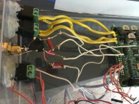
Argh. Trying to test out Spdif but it won't lock. I know it's a bit sloppy but do I have this wired right?
Using the diagram from hifiduino with Spdif+ Spdif- and Gnd
You do not need the transformer. Just have a capacitor in series and 75-110 ohm resistor in parallel.
I installed a digital volume pot on my DAM and found I could only hear noises for all pot positions except the pot was turned to max. volume, which was the only position I could hear the music.
The pot I installed is Tokyo Tocos RV24YN20S B103 10K Linear pot. I tried the pot on two DAMs (V1 and V3) with latest firmware/filters (1021full_106.skr) and both DAMs have the same issue.
Any suggestion and comment to resolve this is highly appreciated.
The pot I installed is Tokyo Tocos RV24YN20S B103 10K Linear pot. I tried the pot on two DAMs (V1 and V3) with latest firmware/filters (1021full_106.skr) and both DAMs have the same issue.
Any suggestion and comment to resolve this is highly appreciated.
differences between dam1021 and dam1121
Hi everyone,
just a short question: What are die differences between dam1021 and dam1121?
I realized that the dam1021 can be powered by AC-voltage and it has an additional buffer output stage. Are there other differences?
Hi everyone,
just a short question: What are die differences between dam1021 and dam1121?
I realized that the dam1021 can be powered by AC-voltage and it has an additional buffer output stage. Are there other differences?
- Home
- Vendor's Bazaar
- Reference DAC Module - Discrete R-2R Sign Magnitude 24 bit 384 KHz