Dear Wineds,
As feed to J2, it skips the onboard diode bridge.
It seems your power connection straightly goes to 100uf capacitors that can skips both diode bridge and 5v regulators. It is very clever, but I don't have skillful hand on soldering and the connection to bridge over the 5v regulators.
My friend and I will try 6 volts power supply this weekend to see if there is a surprise!
Thanks Rick
Rick is wrong with his calculations. The 78L05 has a typical dropout voltage of 1.7v @ 40ma. Add to that 0.7 for the diode bridge => you need at least 7.4V. Anything less will likely result in dropout and /or ripple at the 78L05 output.
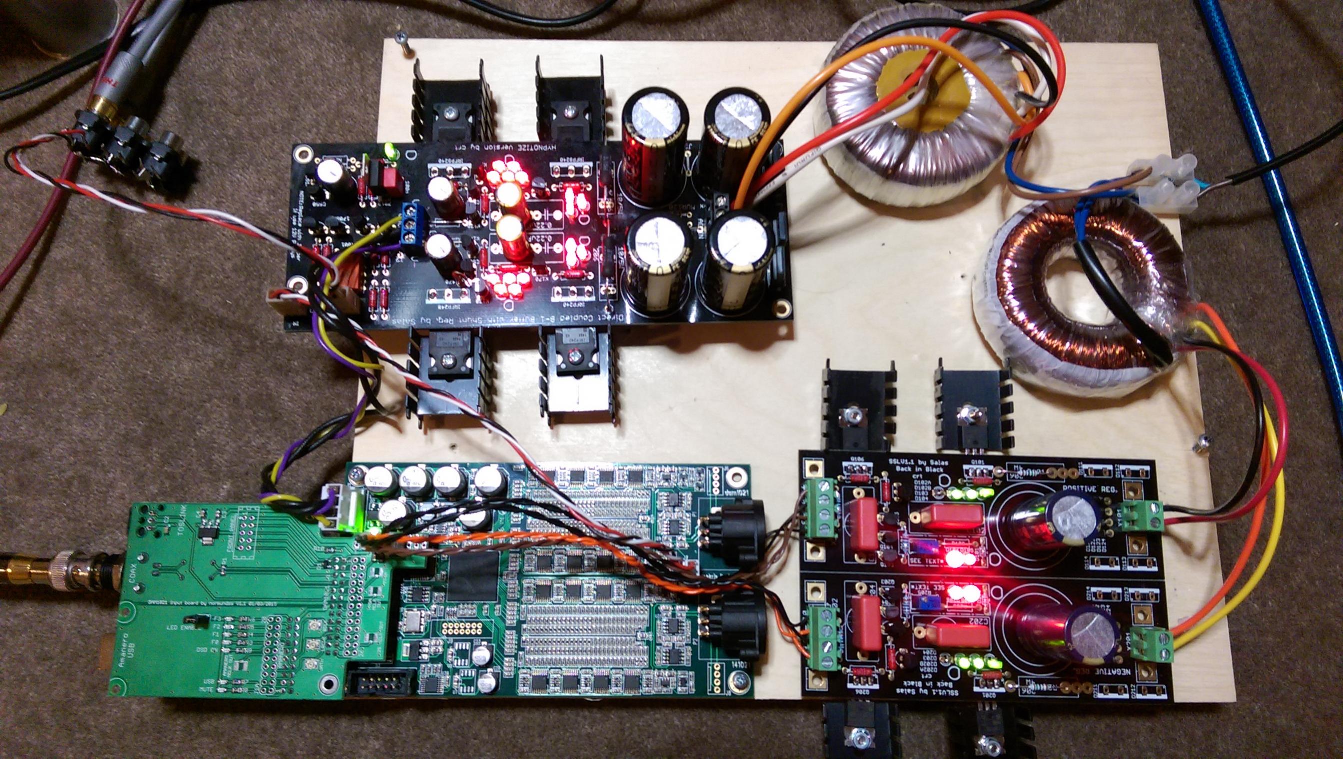
Latest photos of my modified DAM.
1. A 4 pin polarized molex connector has been added to the input board to ensure +/-5V from the Salas shunt is always connected with the correct polarity.
2. Redundant 820uF nichicons have been removed from the board.
3. Panasonic 220uF Oscons substituted for 100uF caps.
4. Panasonic 1000uF Oscon added for local decoupling of V+.
5. Links added to the back of the PCB to aid current delivery.
6. Bridge removed.
7. Output OPAMPS removed.
8. Ladder output RC filter cap moved to back of Salas Hypnotize B1 buffer board. Currently using 1200pF silver mica.
9. Redundant 12 ohm SMD resistors removed.
How is V+ connected for your board? Maybe I'm not understanding something... but isn't it an open circuit when you remove the RC filter?(without shorting out R) I.e. right now it looks like you're powering everything from J2's +-5v input. I don't see how your 1000uF cap is doing anything useful in that config?
Similarly aren't you going to bridge the rectifier pads? When I removed mine I had to do a continuity check to know how to bridge that.
Hi Ristar, V+ is connected via J1. It only runs the digital side of things now. You can see a photo in the link below of how everything is connected.
As for the RC filter, I have only removed the 1200pF capacitor. The capacitor is in parallel with the raw unbuffered output. So I have a 1200pF mica across the input of the B1. Hence electrically there is no change.
The 1000uF just provides some local decoupling of the V+ (~10V) supply (which comes from the Salas Hypnotize board). The bridge is bypassed using the link on the back of the PCB. Only the V+ is connected now.
http://www.diyaudio.com/forums/atta...2r-sign-magnitude-24-bit-384-khz-imag2870.jpg
Last edited:
Hey thanks for the reply... helps me understand. So what I'm saying is the 12R resistors that you removed from the input CRC. Once you remove that... it is in effect an "open" circuit.
Do check if J1 is connected to your V+ and check if your V+ is actually connected to the rest of the board. If I'm not wrong... the last empty pad for the last C after the 12R won't be connected.
If it still is then I've misunderstood how Soren designed the power input for the DAM1021.
Do check if J1 is connected to your V+ and check if your V+ is actually connected to the rest of the board. If I'm not wrong... the last empty pad for the last C after the 12R won't be connected.
If it still is then I've misunderstood how Soren designed the power input for the DAM1021.
Hey thanks for the reply... helps me understand. So what I'm saying is the 12R resistors that you removed from the input CRC. Once you remove that... it is in effect an "open" circuit.
Do check if J1 is connected to your V+ and check if your V+ is actually connected to the rest of the board. If I'm not wrong... the last empty pad for the last C after the 12R won't be connected.
If it still is then I've misunderstood how Soren designed the power input for the DAM1021.
Ok maybe we are referring to different things. By RC filter I man the filter at the DAM raw output. Yes the 12 ohm resistors have been removed. They only feed power to the output OPAMPS so no need for this connection anymore.
Last edited:
Yep. In addition, I just enlarged the shot you took of the underside and got how you bypassed the rectifier now 🙂 (It looked like you just had two wires for the +-5V lines in the thumbnail)
Sorry for the confusion!
Sorry for the confusion!
Last edited:
Yep. In addition, I just enlarged the shot you took of the underside and got how you bypassed the rectifier now 🙂 (It looked like you just had two wires for the +-5V lines in the thumbnail)
Sorry for the confusion!
Ok great. Hope it helps.
Hello,
long time lurker here, this is my first post. 🙂
I think I've read everything I could find about this DAC now. Thanks for all the hard work people are doing to make this possible!
A few questions remain:
1. Now that the dust has settled filters have been optimized - how does the DAC compare (using a low noise PSU)? Is it better than DACs based on the ES9018 at a similar price point? Does it provide the timbral qualities sigma delta DACs are said to be lacking? The feeling of being close to the source, the perception of movement, the liveliness etc.?
Thanks!
Greg
This post discusses a shootout that was performed:
http://www.diyaudio.com/forums/vend...magnitude-24-bit-384-khz-227.html#post4267449
windeds,
AS you know I did not look at the specifications for the 3.3 reg and made a very erroneous assumption. Had no idea it required that much overhead. And I was not considering the diode bridge! (edited this after reading your earlier post) Just bad advice in too many ways.
Thanks for the correction. I hope my "advice" did not cause anyone trouble.
I am not going to use that regulator; will be using a reg with its own power supply in that position and for that reason I have not looked at it and assumed it had a lower dropout than it does. Nothing more dangerous than an assumption.
Thanks for your pictures.
Thanks, again.
Last edited:
This post discusses a shootout that was performed:
http://www.diyaudio.com/forums/vend...magnitude-24-bit-384-khz-227.html#post4267449
Hi MrSlim,
thanks, but I've read that already. However, this test was made before the more recent filter innovations, PSU improvements etc.
What I'm wondering about mostly is if this DAC has the supposed superior "analog" sonics compared to sigma-delta based DACs.
Hi MrSlim,
What I'm wondering about mostly is if this DAC has the supposed superior "analog" sonics compared to sigma-delta based DACs.
Yes it does, to these ears at least. Shares some traits with good turntable setup, in my exp.
No idea which part of the psu upgrade is the most crucial for the Dam, but 2x Ref-d and BiB made a noticeable difference in my rig.
windeds,
AS you know I did not look at the specifications for the 3.3 reg and made a very erroneous assumption. Had no idea it required that much overhead. And I was not considering the diode bridge! (edited this after reading your earlier post) Just bad advice in too many ways.
Thanks for the correction. I hope my "advice" did not cause anyone trouble.
I am not going to use that regulator; will be using a reg with its own power supply in that position and for that reason I have not looked at it and assumed it had a lower dropout than it does. Nothing more dangerous than an assumption.
Thanks for your pictures.
Thanks, again.
Rick McDinnis,
The regulator specification I am referring to is for the 5 volt 78L05.
Input boards V2
I have posted preliminary designs for an updated input board over at the Input and switch boards for Soekris DAM1021 DAC GB thread.
The main new features include
If interested, please sign up or discuss it on the GB thread.
I have posted preliminary designs for an updated input board over at the Input and switch boards for Soekris DAM1021 DAC GB thread.
The main new features include
- Two selectable I2S inputs.
- Raspberry Pi connector
- Flexible external power options for the isolated part/USB/RPi
- Support for DIYINHK USB interface
- Amanero/DIYINHK USB status lines readable from Raspberry GPIO pins.
- Serial port control from Raspberry Pi.
- The 40-pin RPi GPIO connector is replicated on the input board to allow easy connection of other devices, such as a display.
- Everything is designed to fit in a 1U case (40 mm height).
- The locations of USB, COAX and TOSLINK connectors are unchanged from the earlier V1.1 input boards, they will fit previously drilled panels.
If interested, please sign up or discuss it on the GB thread.
Yes it does, to these ears at least. Shares some traits with good turntable setup, in my exp.
No idea which part of the psu upgrade is the most crucial for the Dam, but 2x Ref-d and BiB made a noticeable difference in my rig.
Thank you very much!
Yes it does, to these ears at least. Shares some traits with good turntable setup, in my exp.
No idea which part of the psu upgrade is the most crucial for the Dam, but 2x Ref-d and BiB made a noticeable difference in my rig.
Hi Priidik, Can you post more details of your setup? Maybe some photos? For which power supply rails are you using the BIB and Ref-D?
Hello Soekris,
When will you have the Version with 0.05% in Stock again?
Information is available in the first post. Early Aug 2015.
I'm having some trouble with my second board. I'm just starting to bring it up in preparation for the new firmware etc but in updating the board to the latest firmware, it gets stuck on fpga Rev F.F
It will also automatically go into umanager on power on. Anyone have this problem? I'm trying to test the board with a spdif signal but nothing seems to lock.
Anyone run into this fpga version issue before? If so, how did you get around this?
It will also automatically go into umanager on power on. Anyone have this problem? I'm trying to test the board with a spdif signal but nothing seems to lock.
Anyone run into this fpga version issue before? If so, how did you get around this?
I'm having some trouble with my second board. I'm just starting to bring it up in preparation for the new firmware etc but in updating the board to the latest firmware, it gets stuck on fpga Rev F.F
It will also automatically go into umanager on power on. Anyone have this problem? I'm trying to test the board with a spdif signal but nothing seems to lock.
Anyone run into this fpga version issue before? If so, how did you get around this?
Nevermind... just had to supply the isolators with 3.3v and this was sorted... but it appears I might have botched this board somehow... I get no sound from the right channel for some reason 🙁
Edit: Really strange behavior from this board... on power cycle it won't detect the source again and the Rev goes back to FF until I remove the unbuffered outputs and put it back in again?
Last edited:
- Home
- Vendor's Bazaar
- Reference DAC Module - Discrete R-2R Sign Magnitude 24 bit 384 KHz