I intended that to mean he was the first to do it. He posted a picture in April at TIR NA.
I am sorry I missed that you HAD done it and BRAVO to you for being an intrepid DIY hobbyist that has ALSO beat me to doing this! One thing after another has got in the way.
Now if you are the guy who can figure out how to better the onboard +- 4 volts regulators you will be dearly beloved. I think it impossible but there is nothing I enjoy more than being proved wrong. Please be the man to do it!
Hello,
long time lurker here, this is my first post. 🙂
I think I've read everything I could find about this DAC now. Thanks for all the hard work people are doing to make this possible!
A few questions remain:
1. Now that the dust has settled filters have been optimized - how does the DAC compare (using a low noise PSU)? Is it better than DACs based on the ES9018 at a similar price point? Does it provide the timbral qualities sigma delta DACs are said to be lacking? The feeling of being close to the source, the perception of movement, the liveliness etc.?
My application is pro audio, and in my experience the usual pro audio converters - in varying degrees - take away something fundamental and relevant from the signal compared to a high quality analog source.
2. Is there a schematic for using AES/EBU inputs? I've got the necessary transformers already (salvaged from an old Digidesign converter). My guess would be different resistors values should do the trick.
3. How does one go about connecting power to multiple boards (up to 8)? Using one each of the recommended Salas shunt regulators for +/-, would it suffice to use resistors for isolation and maybe an added filtering capacitor afterwards (since there is on-board-regulation?).
4. Purely out of interest - how much ultrasonic content is produced by the converter using the latest filter at 44.1 khz? Does the digital filter already take care of it or does the passive filter actually remove significant ultrasonic content? How much remains afterwards and might produce slew related distortion in the LME49710?
Thanks!
Greg
Sounds more like a simple manufacturing defect, probably a bad connection somewhere....
As you have done modifications I assume you can do a little troubleshooting, before sending the board back for warranty repair....
1) Is +5V ok ?
2) Is the problem with both channels ?
If so then the problem is around the the -4V to 4V inverter, those parts are at the edge next to J8, look closely for bad solderings....
If you're unable to fix it yourself, send an email to info@soekris.dk for RMA instructions.
Thanks Soren. I did a bit more probing today. There did seem to be a partial solder bridge on the non inverting input of the OAVQ which could have been shorting it to the adjacent V- pin (GND). But I think I have carefully removed it with a sharp pointed hobby knife. Still the issue persists. It looks like the K136 inverting input is stuck at -0.6v when the issue occurs. Possibly some sort of power on device latch up? I might try replacing it.
Last edited:
I intended that to mean he was the first to do it. He posted a picture in April at TIR NA.
I am sorry I missed that you HAD done it and BRAVO to you for being an intrepid DIY hobbyist that has ALSO beat me to doing this! One thing after another has got in the way.
Now if you are the guy who can figure out how to better the onboard +- 4 volts regulators you will be dearly beloved. I think it impossible but there is nothing I enjoy more than being proved wrong. Please be the man to do it!
Based on what I have seen today the on-board +/-4v supply is very good already. If you look closely I am sure Nige can work out how to disconnect it. Whether that has consequences elsewhere I am not sure.
Last edited:
wineds,
sorry to hear you are having troubles.
I tend to agree that the 4 volts regs are likely very good but one never knows until someone, and it won't be me, finds a better solution.
Hope you get the thing sorted quickly. I suspect you will.
sorry to hear you are having troubles.
I tend to agree that the 4 volts regs are likely very good but one never knows until someone, and it won't be me, finds a better solution.
Hope you get the thing sorted quickly. I suspect you will.
Based on what I have seen today the on-board +/-4v supply is very good already. If you look closely I am sure Nige can work out how to disconnect it. Whether that has consequences elsewhere I am not sure.
The + and - 4V supplies have to be carefully matched as they are references as well as power supplies.. To exaggerate, if one regulator is 4.0V and the other is -4.1V, the DAC will produce distortion. This makes using separate regulators problematic.
However it may be possible to tweak the existing supplies. The reference filter of regulators, in my experience, can make a difference to the sound. I don't know what the -3dB point of the filter is, but it may help to lower it. Also the quality of the cap is important too. If it's an X7R it can likely be bettered.
It may also be possible to optimize the output decoupling of the op-amps. If this all sounds rather general, well it's hard to be more specific without actually seeing the circuit.
Seeing this renewed interest in power supplies for the DAM I thought I would tell you what nige2000 has done. I am in the process of getting the parts to copy his efforts.
Nige is a big believer in the A123 28850 batteries. They are the best power supply caps I have ever heard.
Nige is using regulators as floating chargers for the 28850s. He is supplying the DAC with +- 5 volts (you will need a pair of 28850s for each side) and a 3.3 for the clock, etc..
I used these batteries years ago for a Buffalo 1 based DAC for powering AVcc and the clock supply. They worked great. However, it sounds as though you are using they like smoothing capacitors, and keeping the linear supply connected. This nullifies one of the big benefits of using batteries - isolation from noise from the mains, rectifier switching and the regulators themselves.
These batteries are beyond any regulator's capabilities. Their low esr extends much higher in frequency than any regulator I am aware of.
I doubt this - do you have data on impedance for these batteries? I remember seeing a graph some time ago, but can't remember specifics.
Their actual impedance is good, but you can certainly do better with the best discrete regulators. Also, the large size of the batterys, together with the length of connecting wires, will negatively effect impedance at high frequencies.
In my unhumble opinion this is the way and it is not that difficult to implement.
I'm sure the battery approach sounds very good, but I roll my eyes when people start talking about ultimate solutions.
Did not mean to imply ULTIMATE. The system is simple to implement and should sound very good. My only experience is with the computer. I trust Nige's ears concerning the use of them in other places.
No one would be more disappointed than I for the ultimate solution to be found. Sure would ruin the fun. I firmly believe there is no such thing as the ultimate solution. We can agree on that.
What is wrong with them being used as capacitors? After a good series regulator which requires capacitance, anyway. I suspect a battery is better at absorbing back current than a capacitor.
Don't understand the wiring concern. The +-batteries will enter the board with no more wire than a regulator would require. The battery for the clock regulator will be placed so that no more than one inch of wire will be required. The regulators will require some distance, maybe a foot or so, from the batteries. A three pole switch will be used; one for each battery's ground line so turn on will be simultaneous. I will leave it on at all times and hope there is not a power disruption! I will eventually place another three pole switch between the chargers and the batteries grounds.
Ristar and/or wineds, did you use a heat gun or a soldering iron to remove the 5 volts regs?
What is wrong with them being used as capacitors? After a good series regulator which requires capacitance, anyway. I suspect a battery is better at absorbing back current than a capacitor.
The problem is that it misses the opportunity for isolation from all the noise sources present in a typical linear power supply. This is one of the big features of using batteries, IMO.
Don't understand the wiring concern. The +-batteries will enter the board with no more wire than a regulator would require. The battery for the clock regulator will be placed so that no more than one inch of wire will be required.
What about the ground wires? As a battery is significantly larger than a three terminal regulator, the sum of supply and ground wires will be longer, and hence there will be more inductance. You also run the risk of picking up RF noise if there is much flying around.
It's not a deal breaker of course, it's just that I wouldn't claim high frequency impedance as one of the plus points for a battery.
rick: just got back from overseas. I used a heat gun. Do use kapton tape if you can. I misplaced mine and decided to just do without. I ended up spending more time soldering back some SMD resistors that came out or shifted.
Regarding the issue with "crediting," I did suggest that Nigel chime in earlier when we started talking about low noise supplies that I didn't feel the need to shout his name again 🙂 I do think Nigel's contribution was big for me since I didn't realize the rest of the board (save the buffered outputs, of course) worked with just +-5V. I didn't realize this was possible from wineds' reports. Nigel's report basically meant one less power supply for me in my already crowded implementation of a DAC/Preamp.
I haven't spent enough time with the new mods, but first impression was that the 3.3V low noise supply had a bigger impact for me.
ristar,
Thanks for the advice.
You fellows that can solder ultra-small SMD components - I am deeply impressed. I worried soldering would eventually heat the board even more than the heat gun. Yes, kapton tape, in those tight quarters is a must for me since I would never get those resistors back in place.
Looking forward to hearing you full report.
I do not doubt the 3.3 replacement is the big one.
Double BRAVO for the mod and your ability to fix those resistors. Doubly impressive!
spartacus,
I had the same concerns and may end up sharing them but I think you should consider the fact that the battery just might be an excellent filter. I am not so sure that pure battery is all that wonderful either. Plus the main point is: where do you get a five volts battery without float charging it? That is the crux!
So what are you going to use for the 3.3v reg that will allow short wiring? I believe its current requirements will swamp the abilities of the 3 pin TENTs and any other shunt type is going to be large and require some lengthy wiring. So I return to float charging with the BELLESON and figure it will make for a good compromise.
Since I have not yet tried the approach with the DAM I am speculating. Hoping by Saturday I will have it working. BELLESON sent two +5s instead of sending one of each polarity. One thing after another ...
Smt rework
Sorry for the OT post. Kapton tape works well for rework. This also works pretty good. Apply a thin coat get to components around the one you want to remove. Let it cure. Apply hot air to remove the uncoated components. Peel the mask off.
2211-8SQ Techspray | Mouser
Sorry for the OT post. Kapton tape works well for rework. This also works pretty good. Apply a thin coat get to components around the one you want to remove. Let it cure. Apply hot air to remove the uncoated components. Peel the mask off.
2211-8SQ Techspray | Mouser
ristar,
Thanks for the advice.
You fellows that can solder ultra-small SMD components - I am deeply impressed. I worried soldering would eventually heat the board even more than the heat gun. Yes, kapton tape, in those tight quarters is a must for me since I would never get those resistors back in place.
Looking forward to hearing you full report.
Might be a while, have got a clogged nose that's affecting my ears. I hope it will clear up soon.
It actually isn't that hard to fix a few of the smd resistors/caps. I got lucky that I didn't lose sight of the one that dropped out.
Sorry for the OT post. Kapton tape works well for rework. This also works pretty good. Apply a thin coat get to components around the one you want to remove. Let it cure. Apply hot air to remove the uncoated components. Peel the mask off.
2211-8SQ Techspray | Mouser
I didn't know such a thing existed. Thanks for sharing!
Sorry for the OT post. Kapton tape works well for rework. This also works pretty good. Apply a thin coat get to components around the one you want to remove. Let it cure. Apply hot air to remove the uncoated components. Peel the mask off.
2211-8SQ Techspray | Mouser
NEAT! You are certainly not off topic any more than I am!
Thanks for the advice.
The + and - 4V supplies have to be carefully matched as they are references as well as power supplies.. To exaggerate, if one regulator is 4.0V and the other is -4.1V, the DAC will produce distortion. This makes using separate regulators problematic.
However it may be possible to tweak the existing supplies. The reference filter of regulators, in my experience, can make a difference to the sound. I don't know what the -3dB point of the filter is, but it may help to lower it. Also the quality of the cap is important too. If it's an X7R it can likely be bettered.
It may also be possible to optimize the output decoupling of the op-amps. If this all sounds rather general, well it's hard to be more specific without actually seeing the circuit.
Correct. The matching of the +/- 4V is ensured by the precision inverter.
Hi All,
I connect the power supply to the DAM on J2 for more than 2 months now, it sounds good. Lately, one of my friends lower down the DC voltage from 9V to 8V. The sound is more dynamic with better quality of bass. It seems that 8V is more close to the reference voltage to 5V regulators. Just curious if what components drain the power through the path from J2 to 5V regulators and if further lower down the input DC voltage close the minimum 7.5V, will it sounds better.
I connect the power supply to the DAM on J2 for more than 2 months now, it sounds good. Lately, one of my friends lower down the DC voltage from 9V to 8V. The sound is more dynamic with better quality of bass. It seems that 8V is more close to the reference voltage to 5V regulators. Just curious if what components drain the power through the path from J2 to 5V regulators and if further lower down the input DC voltage close the minimum 7.5V, will it sounds better.
Hi All,
I connect the power supply to the DAM on J2 for more than 2 months now, it sounds good. Lately, one of my friends lower down the DC voltage from 9V to 8V. The sound is more dynamic with better quality of bass. It seems that 8V is more close to the reference voltage to 5V regulators. Just curious if what components drain the power through the path from J2 to 5V regulators and if further lower down the input DC voltage close the minimum 7.5V, will it sounds better.
With a low dropout regulator all of the excess voltage is wasted and probably screws things up.
If you are not using the output stage 6 volts DC is probably just right! If you have a pair of 4 volts (AC) transformers you should give it a try. Yes, this will result in approx 5.6 volts - plenty for the 3.3 and 5 volts regulators.
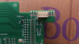
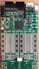
Latest photos of my modified DAM.
1. A 4 pin polarized molex connector has been added to the input board to ensure +/-5V from the Salas shunt is always connected with the correct polarity.
2. Redundant 820uF nichicons have been removed from the board.
3. Panasonic 220uF Oscons substituted for 100uF caps.
4. Panasonic 1000uF Oscon added for local decoupling of V+.
5. Links added to the back of the PCB to aid current delivery.
6. Bridge removed.
7. Output OPAMPS removed.
8. Ladder output RC filter cap moved to back of Salas Hypnotize B1 buffer board. Currently using 1200pF silver mica.
9. Redundant 12 ohm SMD resistors removed.
Attachments

Last edited:
Dear Wineds,
As feed to J2, it skips the onboard diode bridge.
It seems your power connection straightly goes to 100uf capacitors that can skips both diode bridge and 5v regulators. It is very clever, but I don't have skillful hand on soldering and the connection to bridge over the 5v regulators.
My friend and I will try 6 volts power supply this weekend to see if there is a surprise!
Thanks Rick
- Home
- Vendor's Bazaar
- Reference DAC Module - Discrete R-2R Sign Magnitude 24 bit 384 KHz