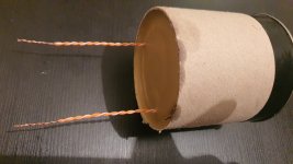
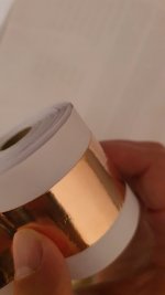
Hi. After a long time of job "grinding", i finally have some time for myself. So next to some serious projects (amp, speakers), i have went on to create something i wanted to do for a long time, and make pio capacitor. Had 20m of copper 0.05mm foil laying around and i wound myself a 0.4uF cap (pics in attachment), since i have access to both machines that can roll it tight, and vacuum chamber. Vacuumed with mineral oil, and encased in wax. Now i have been told to pay attention to inductance of such a capacitor. I have only connected leads to the ends of both foils (each foil is 10m).
Which leads me to this topic and the question at hand. What is the best way to reduce inductance in such a capacitor? How does duelund and the rest do it? What i have managed to pickup from the videos and photos, they leave extra foil on each side (so conductor/foils are not completely parallel, and one side protrudes from one foil, and the other side protrudes with another foil), and i guess they connect somehow those edges on each side (which can't be seen, but it's my best guess).
Which leads me to this topic and the question at hand. What is the best way to reduce inductance in such a capacitor? How does duelund and the rest do it? What i have managed to pickup from the videos and photos, they leave extra foil on each side (so conductor/foils are not completely parallel, and one side protrudes from one foil, and the other side protrudes with another foil), and i guess they connect somehow those edges on each side (which can't be seen, but it's my best guess).
Attachments

Stacked plates, not rolled, basically, so current can flow over the surface directly to every plate via an equally short path. In short timescales current flows on the surface (skin effect), not through metals. Or put another way have all the individual plates in parallel, not series.
ah, so instead of two very long leaves wound together in a spiral (from center to edge), you would have many leaves of copper, shuffled like cards.
all of the left deck connected together to one terminal; similarly for the right.
Is that the idea, @Mark Tillotson ?
Kind regards,
Drew
all of the left deck connected together to one terminal; similarly for the right.
Is that the idea, @Mark Tillotson ?
Kind regards,
Drew
That is the idea. As example look at these Siemens MKM https://www.google.com/search?q=sie...Pgf0HHVyNDDQQ9QF6BAgyEAE#imgrc=d-9m3YAXllEGdMah, so instead of two very long leaves wound together in a spiral (from center to edge), you would have many leaves of copper, shuffled like cards.
all of the left deck connected together to one terminal; similarly for the right.
Is that the idea, @Mark Tillotson ?
Kind regards,
Drew
I've never really grasped this. You have two electrodes. Current travels up one and down the other. It cancels out most of the inductance, in spite of the wound structure. Have you measured the inductance or self-resonance. Most inductance ends up being a result of the physical size and lead length, not the construction. Or at least that's what I think until somebody shows me how it's different.
+1. Find out first whether there is a problem.Have you measured the inductance or self-resonance.
Have a look at the DNM Products, the T-Network Capacitor or the Mundorf version of 4 pole capacitors and how they're made - unfortunately, Jensen's versions are no longer made - unsure if the designs are still available
According to the Duelund website they use a "Virtual Stack Foil" construction. Whatever that means. I'm not seeing any specs regarding the SRF or ESR for the Duelund caps, so maybe OP's is just as good. Just not as pretty. 🙂
Tom
Tom
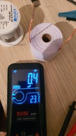
I haven't measured inductance yet, haven't got around to it (get a meter for inductance).
Will update as i do it.
Meanwhile i got myself 3600 meter of aluminum foil (8cm width) and waxed paper 🙂 For around 30$, so much cheaper to experiment with.
Will update as i do it.
Meanwhile i got myself 3600 meter of aluminum foil (8cm width) and waxed paper 🙂 For around 30$, so much cheaper to experiment with.
Yes, that's a non-inductively wound film cap for instance. Its possible to wind inductively too (why one would I don't know!). But any wound capacitor will be worse in high frequency performance than a stacked plate capacitor due to length of the current path. The current path length limits the wavelength of any RF signal the cap can handle and remain fully capacitive (if the unwound length of the foils/film is several metres, its hardly a lumped component at VHF!). However often the lead inductance is an issue too, which is why SMT MLCC's perform way better at HF - short wide trace over ground-plane direct to stacked plates.I've never really grasped this. You have two electrodes. Current travels up one and down the other. It cancels out most of the inductance
- Home
- Design & Build
- Construction Tips
- Reducing diy capacitor inductance