I'm trying to find ways to attenuate my CD player's output for use with a vintage amplifier. RCA attenuators are too expensive (can't find cheaper than €50 to get a pair in Belgium). So I see only 2 cheap and easy fixes:
- Put in an Opamp with less gain. Are there any dual Opamps with 6dB less gain than for example NE5532?
- Add 2 resistors per channel (one in series, one to ground) after the Opamp stage. I'm fully aware that it's better to put these at the amplifier's input but what's the difference if I put them at the CD player's output? More high frequency roll-off? My hearing craps out at 16kHz so I'm not too worried about that.
CD players I have are Philips CD710, CD634 and CD620. The latter two have variable gain output so I could play around with that without any mods. The CD710 however does not and will require a mod.
Putting in an opamp with "less gain" will make no difference whatsoever, as the circuit gain is determined by feedback components (usually resistors) and not the opamps.
Adding an attenuator will do the trick. This should be at the amp end, not the CD player end, unless you are happy to lose treble due to the cable capacitance. If the cable is short then this doesn't matter.
Adding an attenuator will do the trick. This should be at the amp end, not the CD player end, unless you are happy to lose treble due to the cable capacitance. If the cable is short then this doesn't matter.
Thank you. If I put the attenuator at the CD player end, how do you think treble will be affected? Will everything below 16kHz be untouched?
Use something like 6k8 feed resistor and determine the second shunt element of the attenuator by listening until the level suits. Any CD player will drive loads down to at least 2K, in practice quite a bit lower.
The treble won't be materially affected.
The treble won't be materially affected.
If you use 6k8 and have a cable capacitance of say 200pf then the -3db point is way over 100kHz. You can go lower than 6k8. Try a 2k2 and say 680 ohm as a shunt if your old amp is really sensitive.
Nooo 🙂 I wouldn't do that. The stage isn't a gain block, its an I/V convertor. What about the coil and the cap ?
What you could do is just add a resistor across the 1nf cap at the output. Adding 1k would cut the level in half.
What you could do is just add a resistor across the 1nf cap at the output. Adding 1k would cut the level in half.
If you use 6k8 and have a cable capacitance of say 200pf then the -3db point is way over 100kHz. You can go lower than 6k8. Try a 2k2 and say 680 ohm as a shunt if your old amp is really sensitive.
I saw your post before from a few years ago. Is that the recommended position for the resistors or can I put them after the coupling capacitor right before RCA outputs?
Nooo 🙂 I wouldn't do that. The stage isn't a gain block, its an I/V convertor. What about the coil and the cap ?
What you could do is just add a resistor across the 1nf cap at the output. Adding 1k would cut the level in half.
Any disadvantages of that over the other method (with 2 resistors)? So 1k would be -3dB, 4k -6dB?
Also, does it make a difference if I use cheap film resistors vs more expensive ones?
Last edited:
The earlier post was player specific, in just the same way that this one is 🙂
There is no disadvantage with adding a resistor across the 1nf cap, its achieving the same thing. In this case you have a nice 1k to use as part of the attenuator, in the earlier thread there wasn't anything suitable without changing those 100 ohms. I have spotted one thing though, and this would apply to an external attenuator as well, and that is that the coupling cap 2306 in the above diagram could do with increasing by a factor of 10 to 47uf. That will preserve the low frequency response of the stage.
There is no disadvantage with adding a resistor across the 1nf cap, its achieving the same thing. In this case you have a nice 1k to use as part of the attenuator, in the earlier thread there wasn't anything suitable without changing those 100 ohms. I have spotted one thing though, and this would apply to an external attenuator as well, and that is that the coupling cap 2306 in the above diagram could do with increasing by a factor of 10 to 47uf. That will preserve the low frequency response of the stage.
The resistor quality will have no effect. Use standard 0.25 or 0.6 watt metal films.
The really important thing is for you to make sure your player really is the same as the one in the diagram. If the 1k resistor is different then the attenuator would not work correctly without altering. Once you know what you have then its only a minutes work to pick suitable values.
The really important thing is for you to make sure your player really is the same as the one in the diagram. If the 1k resistor is different then the attenuator would not work correctly without altering. Once you know what you have then its only a minutes work to pick suitable values.
If your not sure then ask 🙂
The important things are that the max load on the opamp isn't to high. All the ones in these players can drive 600 ohms so we have no worries there. So you choose your series resistor value... here you have a 1k that's already suitable... and so you just add another resistor from the output end of the 1k to ground. The lower the value, the less signal you get. Even if you shorted the output to ground the opamp still sees the 1k series feed.
If the player was different... say it was like the other example with two series 100 ohms and two muting transistors . Here you could increase the two 100 ohms to say 560 ohms and then add your attenuating resistor to ground in the same way.
In all cases the coupling cap needs to be big enough to maintain bass response into the worst case load, which we will say is 1k. That puts a value of around 47uf on the coupling cap.
Yes 🙂 yes 😉
Hi,
I used to knock up CD cables with the attenuator built into the
amplifier far end phono plugs, 4.7K to 6.8K series, 1K parallel.
There is no chance of any treble loss.
rgds, sreten.
I used to knock up CD cables with the attenuator built into the
amplifier far end phono plugs, 4.7K to 6.8K series, 1K parallel.
There is no chance of any treble loss.
rgds, sreten.
It's the same as in Impuls' diagram. So I use 1k in series with the coupling cap and 1k across the 1nf cap? Could I also do the 1k resistor without any resistor in series?
Also, how do I calculate the values?
Forgot to mention I also have a Philips CD610, CD615 and CD471.
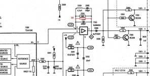
Here's my CD610 for example:

CD615:

CD471:

CD620:

Also, how do I calculate the values?
Forgot to mention I also have a Philips CD610, CD615 and CD471.
Here's my CD610 for example:
CD615:
CD471:
CD620:
Last edited:
Posted too soon. Just saw your last post, Mooly, which seems to answer most of my questions. Thanks!
All the players I posted above have two resistors in series so I increase the values x5. Where do I put the attenuating resistor though? There already a 10k resistor there going to ground. I could add a 1k resistor parallel with that one?
All the players I posted above have two resistors in series so I increase the values x5. Where do I put the attenuating resistor though? There already a 10k resistor there going to ground. I could add a 1k resistor parallel with that one?
put 2 10k to 20k trim pots in the amp on the input you want to use.
pin 1 ground , pin 3 signal , pin 2 goes to amp
you just cut the signal trace close to the input
Adjust each channel accordingly.
pin 1 ground , pin 3 signal , pin 2 goes to amp
you just cut the signal trace close to the input
Adjust each channel accordingly.
Stabby just do it as i wrote, nothing more
Sorry, too risky. Putting a resistor in that place could noticeably affect sound. I'd give it a try if several other people can confirm it's okay.
put 2 10k to 20k trim pots in the amp on the input you want to use.
pin 1 ground , pin 3 signal , pin 2 goes to amp
you just cut the signal trace close to the input
Adjust each channel accordingly.
Wouldn't it be a lot of work balance the left and right channels with trim pots?
Maybe making my own cable would be easier and less work than inserting an attenuator in every single CD player. I'll try putting some resistors in the CD710 though.
Not sure about Belgium, but here in the US, eBay is full of 1970s stereo components selling for very little. A simple preamp would do the trick and would probably be worth the $40 bucks or so as a handy switcher too.
Making your own making Attenuating rca plugs
Quad sells attenuating cables, which is the easiest solution.
Quad sells attenuating cables, which is the easiest solution.
Nonsense, current output of the DAC and i/v the resistor will affect the sound, but put 1k from out to ground after 4u7 capacitor will not?
Learn how to use the opamp for i / v conversion and everything will be clear in mind
On picture for cd610, cd471 and cd620 is lowpas filter, on picture for cd615 is gain stage
Learn how to use the opamp for i / v conversion and everything will be clear in mind
On picture for cd610, cd471 and cd620 is lowpas filter, on picture for cd615 is gain stage
Last edited:
- Status
- Not open for further replies.
- Home
- Source & Line
- Digital Source
- Reducing CD player output: suggestions?