as I did explain with funny sketches, it is relatively important to obtain same/similar value of resistances going from rails to biasing core
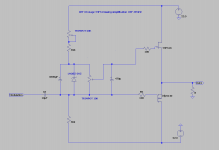
there is also way to achieve it here, adding string of 4 green diffuse LEDs (simplest most common ones)
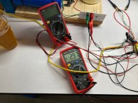
observe:
-voltage at top of led string, resistance above;
-voltage at gate of IRFP, resistance bellow
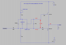
there is also way to achieve it here, adding string of 4 green diffuse LEDs (simplest most common ones)
observe:
-voltage at top of led string, resistance above;
-voltage at gate of IRFP, resistance bellow
Attachments

Last edited:


yeah, principle is what counts, so - you got it
🙂
looking at numbers at your schematic - with 60+ Watts at tiny mosfet, take extreme care about heatsinking and thermal arrangement
frankly, with 60W ....... maybe better to resort to mosfet in puck case (see which candidates in Babelfish XA252 thread)
and - it will work ......
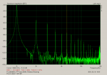
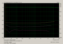
though - I tried it in SissySIT (R.1) eons ago, I wasn't overly impressed with results comparing to regular TO247 IRFP9140
with puck down, per my faint memory (lazy to compare now with regular SissySIT graphs) ........ THD was funny - worse than with IRFP9140
anyway - here they are, do comparison with graphs here : https://www.diyaudio.com/community/threads/sissysit-r-3.371272/post-6626308
it would be interesting to try it in SissySIT R.3, that resulting in firmer control of P channnel mosfet gate, needed for puck one
but ...... naah ........ I'm not going to bother
🙂
looking at numbers at your schematic - with 60+ Watts at tiny mosfet, take extreme care about heatsinking and thermal arrangement
frankly, with 60W ....... maybe better to resort to mosfet in puck case (see which candidates in Babelfish XA252 thread)
and - it will work ......
though - I tried it in SissySIT (R.1) eons ago, I wasn't overly impressed with results comparing to regular TO247 IRFP9140
with puck down, per my faint memory (lazy to compare now with regular SissySIT graphs) ........ THD was funny - worse than with IRFP9140
anyway - here they are, do comparison with graphs here : https://www.diyaudio.com/community/threads/sissysit-r-3.371272/post-6626308
it would be interesting to try it in SissySIT R.3, that resulting in firmer control of P channnel mosfet gate, needed for puck one
but ...... naah ........ I'm not going to bother
Attachments
Last edited:
Yes, I will do it slowly slowly with my heatsink. hope it work fine ~ 1.7A .
I will spent time later to find sweet point to cancel harmonic.
I will spent time later to find sweet point to cancel harmonic.
with proper heatsinking, TO247 + ZM Chicken - no more than 50W per device
Keratherm or Al Oxice pad + goop
Keratherm or Al Oxice pad + goop
Hi ZM,
so I have neither 3300uF nor 470uF in my meager project box, but what I do have are 220uF, 1000uF, 2200uF, 4700uF and 6800uF electrolytics at my disposal. Without goofing up any time constants, what if any combination of these could I use in place of the 3300/470 arrangement?
so I have neither 3300uF nor 470uF in my meager project box, but what I do have are 220uF, 1000uF, 2200uF, 4700uF and 6800uF electrolytics at my disposal. Without goofing up any time constants, what if any combination of these could I use in place of the 3300/470 arrangement?
Cheers and thank you. Trying to do this completely with scrounged or leftover parts. I think I have a source for the trimpots and carbon resistors, but that Zener devils me. all I have are 20V or 9.1V Zeners at the moment.not critical at all
use 2200 and 220
you need to use prescribed part, for best operation
it is crucial that reference is stable with minimal current - as I already noted
of course, you can use whatever you want as reference for initial tests, but remember that current through vertical path ( upper rail resistor, everything between gates, lower rail resistor) is sorta 500uA
so, LM385-2V5 is pretty much cheapest, while also probably the best
Hi ZM, so I got some of the LM385-2V5's at a local place so that's good, but I'm confused about something else now.
The IRFP9240's I have are behaving like enhancement mode devices, with Vgs in the 4.1V range. My Frankentracer testing of my SITs didn't test for Vgs in the same way, but the turn-on voltage of them is right around -5.7V. I'm confused as to which of the circuits to use as they seem to all show negative gate bias voltages for the IRFP9240, while my devices are all quite positive.
Also it would be much easier for me to build this single rail with coupling caps as I don't have an unused dual rail power supply.
Last edited:
IRFP9240 , source up, more positive than gate, so Ugs is negative
state MOS Ugs value for desired rail and Iq
SIT, source down, more positive than gate, so Ugs negative
state SIT Ugs value for desired rail and Iq
drawing and making that circuit is trivial, give me written above
state MOS Ugs value for desired rail and Iq
SIT, source down, more positive than gate, so Ugs negative
state SIT Ugs value for desired rail and Iq
drawing and making that circuit is trivial, give me written above
Hmm. Extrapolating from my primitive curve tracing, a 19V rail at 1.5A is a SIT Ugs between -3.0V and -3.2V. For the MOSFETs, the potential differences from source to gate (aha! opposite in sign of gate to source! must flip the sign to negative!) were between 4.09V to 4.13V at 15V and 0.21A, because that's how I measured my N-channel MOSFETs last time & was trying to match them for other projects. So a little more than a volt of difference between the gates unless the higher current will substantially change the MOSFETs Ugs (to pass more current, more negative?). For a MOSFET Ugs that's more negative than the SIT, it's the schm below, right?IRFP9240 , source up, more positive than gate, so Ugs is negative
state MOS Ugs value for desired rail and Iq
SIT, source down, more positive than gate, so Ugs negative
state SIT Ugs value for desired rail and Iq
drawing and making that circuit is trivial, give me written above
I know Ben Mah recommends operating points of 33-35V, 2.2-2.5A for 2SK180's, but for now I would like to use my cheap and free 19V single rail laptop bricks for this. Idc about distortion, I can hear it but not measure it rn anyway.
Attachments
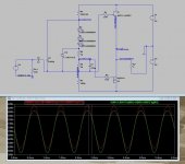
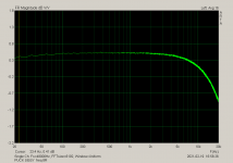
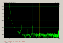
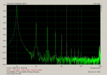
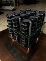
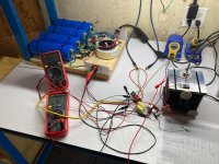
So I made one of these. It took a while as I had to first make a dual rail bench PS using some leftover parts and some free ancient capacitors from a recent group buy. The PS has measurable AC ripple in this iteration of about 20mV, as I'm only using two capacitors per rail (C-R-C), but it puts out 46.3V rail to rail, loaded. Good enough for government work.
I used a THF-51S SIT with a target gate bias of -3.2 to -3.0V, paired with an IRFP9240 with a Vgs of -4.14. It was pretty easy to get DC offsets of 0.03V or less and stable, first with an 8R power resistor and then later with a 4" Fostex speaker as load, using ZM's circuit. Initial operating points for the SIT were -3.8, then -3.27, then I let it run a while at -3.02V playing music. This amp got hot. At first the SIT was 46C, then later as high as 55C; the MOSFET and heatsink were 70C (!) after about a half hour when I shut it down. The SIT gate bias crept from -3.02V down steadily to -2.96V over that time, so some thermal runaway I guess.
As for the sound? Idk man, it played music reasonably well and all, but I think this configuration must not have much gain as the volume didn't get anywhere near as loud as my F3 does with the same source and speaker. I'm thinking a proper SIT amp needs a front end gain stage. Maybe one of ZM's SissySITs if I can get the boards?
Attachments
that circuit needs proper cooling , meaning - steady temperature around 50C at sink max. and bespoke thermal arrangement for mosfet, some less critical for SIT ( due to sheer size of case)
and final settings are done only in temp equilibrium; previous behavior ( Iq and Offset) being interesting only as values of importance for your speakers ( DC)
sorry, that's Nature of The Beast, and you must arrange it that way, or going more complicated way electrically - just take a look at developing of SissySIT
and yes, that circ is DEF , which means Depletion-Enhanced-Follower, meaning - no voltage gain at all
so, either put buffer+autoformer in front (getting M2 derivative, later DEFiSIT) or any decent active gain stage
yup, ZM is still having everything for SissySIT R.3 and soon hope to have even (42), as result of playin' with 2SK2087C
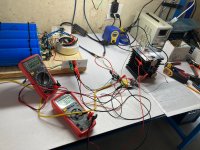
The DC offset was remarkably stable once the amp channel was on and warm. Although at power on there was close to 2V of offset as presumably the power supply caps settled down. The speaker didn't scream so I called it okay.and final settings are done only in temp equilibrium; previous behavior ( Iq and Offset) being interesting only as values of importance for your speakers ( DC)
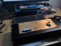
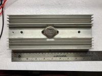
I have a pair of salvaged heat sinks that I machined out to take 2SK180s. They are a little more than 245mm long, and while I do not have any other parts yet to turn them into a proper chassis, I intend to do so at some point. Would any of your SissySIT boards fit lengthwise behind that heat sink?yup, ZM is still having everything for SissySIT R.3 and soon hope to have even (42), as result of playin' with 2SK2087C
Attachments
plenty of pics with exact measurements in related threads
post #10
that sink on your pic ........ smallish, loud forced cooling is first what comes to mind
and, having both OS devices of same channel - on shared heatsink is extremely wise
any amp with these parts is deserving proper build
I like dumpster diving, that's my second nature ..... but sometimes you simply need to find better dumpster
- Home
- Amplifiers
- Pass Labs
- Redneck ZM DEFiSIT/DEF biasing