Hi all, I'm back again with another (probably quite simple) question...
I picked up a so-so, incomplete DIY amp a little while ago that somebody else made. It's ugly, real ugly--what I'm using it for, more than anything else, is a good source of spare parts")
Anyway, I have traced the circuit to discover that the rectifier on the existing circuit is as illustrated in the attachment. Frankly, I'm stumped as to how it manages to work...
That is, with the two diodes wired in as they are, it would seem that this should only be a half-wave rectifier, but it's clearly not since the B+ voltage is 315V (measured). And what are the capacitors I've labelled C1 (with .01M Z5U printed on them) supposed to be doing?
I'm OK with how the B+ supplies work, I'm just a bit confused as to why this rectifier is configured the way it is, and how it manages to work. Any insight would be greatly appreciated!
(As you may have guessed, I'm not an electrical engineer )
Many thanks in advance.
I picked up a so-so, incomplete DIY amp a little while ago that somebody else made. It's ugly, real ugly--what I'm using it for, more than anything else, is a good source of spare parts
Anyway, I have traced the circuit to discover that the rectifier on the existing circuit is as illustrated in the attachment. Frankly, I'm stumped as to how it manages to work...
That is, with the two diodes wired in as they are, it would seem that this should only be a half-wave rectifier, but it's clearly not since the B+ voltage is 315V (measured). And what are the capacitors I've labelled C1 (with .01M Z5U printed on them) supposed to be doing?
I'm OK with how the B+ supplies work, I'm just a bit confused as to why this rectifier is configured the way it is, and how it manages to work. Any insight would be greatly appreciated!
(As you may have guessed, I'm not an electrical engineer
)Many thanks in advance.
Attachments
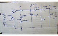
This is a half wave voltage doubler. The lower 100uF capacitor is charged to the peak winding voltage by the lower diode on the first half of the sine wave. The upper capacitor is also charged to the peak winding voltage but this time by the upper diode on the second half of the sine wave. The output voltage is the sum of the two capacitor voltages and double the transformer voltage.
This kind of design has poor ripple (60Hz instead of 120HZ like a full wave bridge) and poor output regulation (double the winding Ohms and double the capacitor droop).
This kind of design has poor ripple (60Hz instead of 120HZ like a full wave bridge) and poor output regulation (double the winding Ohms and double the capacitor droop).
I am going to have to respectfully disagree with hermanv. This is a full wave voltage doubler and I use them all the time and like them. The thing you have to remember with them is that they double the voltage capability of the transformer but they also halve the current capability. (you can't get something for nothing)
SpreadSpectrum is correct. That topology is known as a full wave voltage doubler. Some justification for the name exists. The ripple freq. is 2X that of the AC mains and both halves of the sine wave are used.
Properly executed, "full wave" doubler B+ PSUs are quite good. Some of the best units ever made employ the topology. The H/K Cit. 2, Marantz 8B, and Fisher 500C are examples.
LARGE caps. are appropriate in the doubler stack. Large 1st filter caps. imply a small conduction angle and a good deal of ripple overtone energy. Follow the doubler stack with a low DCR inductance and more capacitance. Think "extended" CLC filter. A H/K Cit. 2 overhauled ala Jim McShane kicks serious butt. Jim replaces the OEM doubler caps. with low ESR 820 muF. Panasonic 'lytics. The rest of the B+ PSU is beefed up too.
FWIW, we used something quite similar, at a lower current, in "El Cheapo" and (unsurprisingly) obtained highly satisfactory performance.
TANSTAAFL applies and the available DC current is approx. 1/4 the AC RMS current of the rectifier winding.
Yeah, a google search revealed that I have a full-wave doubler here, not a half wave, but that's OK.
However, the poor voltage regulation is a very real thing--I worked out the transfer function for the whole thing, and compared the actual (measured) results with the computed ones (assuming a true DC input signal) to find some reasonably large discrepancies. This is now easily explained by both the 100 Hz ripple current (2x AC mains frequency) and the undersized caps. The two factors combined effectively mean that the filtering is less than what it needs to be.
Either way, I have once again learned a bundle--best forums ever
As well, I'm planning on doing things differently in the upcoming build anyway--full wave rectification via an RCA 82, with the input coming from a purpose built transformer (no voltage doubler or anything).


wally,
I agree. Why double when you can just get the transformer made right? I just got a transformer quoted for a new project of mine and I went with bridge rectification to eliminate the center tap on the secondary. Why make it more complicated than it needs to be? The transformer was really cheap since its just got two wires going in and two coming out.
I mostly use doublers when I need a -15V supply and want to use a spare 6.3V winding. I've also needed +12V supplies and doublers on 6.3V windings work great for that too. I don't think I'd use a doubler on the main supply personally because I like simple and elegant solutions.
Oh yeah, 100Hz.
I've always had good luck with Signal Power Transformers, quick shipping, reasonable pricing, good choice of standard models. This leads to a PDF catalog download: (5.8 Megabytes)
http://www.signaltransformer.com/Data/UploadedFiles/signalcatalog.pdf
For more exotic toroids there's Plitron.
http://www.plitron.com/
http://www.signaltransformer.com/Data/UploadedFiles/signalcatalog.pdf
For more exotic toroids there's Plitron.
http://www.plitron.com/
Doublers don't have poor regulation... but undersize transformers do.
The only real disadvantage of the doubler vs. the full-wave bridge is the additional ripple current in the input caps, which is at line frequency, not 2 * F. Either one beats the full-wave center-tap circuit by getting 40% more from a transformer for the same regulation (or temperature rise).
The only real disadvantage of the doubler vs. the full-wave bridge is the additional ripple current in the input caps, which is at line frequency, not 2 * F. Either one beats the full-wave center-tap circuit by getting 40% more from a transformer for the same regulation (or temperature rise).
Whut Tom sez. A fullwave doubler may have a little less load regulation in theory, but in practice most of the difference will be due to using the transformer at twice the supply output voltage, and thus half the current rating.
In any event, since the lower voltage transformers that are good candidates for this rectifier circuit are relatively plentiful and cheap, we can afford plenty of transformer rating. Also, as purist audio geeks, many (if not most) of our circuits will be operating in class A, and so load regulation becomes a nonissue, the load remaining relatively constant.
I like the fullwave doubler, use it all the time. In a world where high voltage transformers are scarce and expensive, and low voltage ones are not, it' a godsend. It's sometimes the only way I can get a 'tweener' voltage, like a tail negative supply.
Aloha,
Poinz
Tom, I guess you lost me.
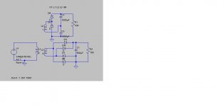
For the non center tapped case, a full wave bridge has 1/2 the transformer current of the voltage doubler but needs 2 times the number of turns, For the same wire gauge I^2R comes out the same for both cases, same heat same voltage.
Why this changes if you add a center tap escapes me unless you discard the minus voltage and ground the center tap, but that isn't an apples and apples comparison. Did you find the proverbial free lunch?
L3 has 4 times the inductance of L2 (so twice the number of turns)
V R1 = V R2
Ripple is the same for both.
I L2 = twice I L3 (I assumed 99% coupling coefficient).
Attachments
Comparing the doubler to full wave bridge... if you unwind half the secondary you have half the resistance... but you also have room to wind on more wire, which you could connect in parallel to get 1/4 the resistance.
Let's say we have three transformers, all with the same amount of copper in them. First is 120V, 2.5 Ohms. Second is 240V, 10 Ohms. Third is 480VCT, 20 Ohms per half. The first two will perform almost exactly alike, using a doubler and FWB, respectively. The third with FWCT will lag behind, since the two halves carry current alternately, not continuously. So only half of the secondary is carrying the output current at any instant. You'll need 40% more copper in the secondary to provide the same output as the other two. Of course, FWCT is the only reasonable choice with tube rectifiers...
Let's say we have three transformers, all with the same amount of copper in them. First is 120V, 2.5 Ohms. Second is 240V, 10 Ohms. Third is 480VCT, 20 Ohms per half. The first two will perform almost exactly alike, using a doubler and FWB, respectively. The third with FWCT will lag behind, since the two halves carry current alternately, not continuously. So only half of the secondary is carrying the output current at any instant. You'll need 40% more copper in the secondary to provide the same output as the other two. Of course, FWCT is the only reasonable choice with tube rectifiers...
Hmm, some debate has been sparked! Here's a question then:
I fully agree with the post way back there that says that a *well designed* output doubler would perform wonderfully. It's the well designed bit, though, that will push up the cost... But let's say for now that that is not a consideration, how many times do you think one could effectively multiply the voltage and still have a useful B+ supply? Theoretically I realize you could go to infinity, but I'm wondering about realistically.
BTW, as for transformers, I have had things built by these guys in the past--very reasonably priced, great workmanship, and they'll build you pretty much whatever you want. Except maybe a sandwich. Handy!
Wally,
For anything resembling a significant current draw, 4 or 5 fold multiplication is (IMO) a realistic limit. The losses begin to mount.
There are a number of voltage multiplier topologies that can be used. Look here. That last circuit has the potential to turn a power trafo salvaged from a SS power amp into something useful, but the costs are not low. 'Lytics are fine in the central "spine". Because AC is carried in the "arms", motor run caps. seem appropriate in those positions. Follow the multiplier with a "hash" suppressing choke and a final reservoir capacitor.
In my own research, I have only seen full-wave doublers; all the higher multiples are single wave, which I regard as a considerable disadvantage; ripple amplitude twice as high and frequency half as high. Four times as difficult to filter. All those circuits use the half-wave doubler configuration, simply cascading it over and over to get higher multiples. I have that circuit archived somewhere; if somebody wants to see it, I'll dig it up and make some pictures.
I wouldn't do it otherwise, I consider it to be a nonoptimum solution.
Aloha,
Poinz
I wouldn't do it otherwise, I consider it to be a nonoptimum solution.
Aloha,
Poinz
- Status
- This old topic is closed. If you want to reopen this topic, contact a moderator using the "Report Post" button.
- Home
- Amplifiers
- Tubes / Valves
- Rectifier query