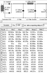
There are always beefier parts. I learnt the importance of reverse voltage with this supply using CSD01060A which have a rating of 600v. I looked at my PSUD sim and seen 450v at the first filter cap and though it good to go. Wrong, turns out the difference across the diode can be over 900volts.
I can tell you from experience the 600v parts last about 2-3 minutes before failing and blowing the fuse. The transformers make some real angry noises when that happens...
I can tell you from experience the 600v parts last about 2-3 minutes before failing and blowing the fuse. The transformers make some real angry noises when that happens...
Attachments
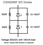
Does this look like it would work? Not sure of the wattage of the resistors or the voltage rating of the caps.
Looks very good to me. Simply wiring high PIV Schottky diodes in series is known to be unsatisfactory, with cascading failures occurring. You have voltage equalizing resistors that protect both the Schottky diodes and the filter capacitors.

As for the power rating of those resistors, 1 of the established formulas should help.
P = V2/R
Definitely allow for lots of "fudge" in both the WVDC and power departments.
That will work fine. Increase the number of series parts sets if you use this idea on higher voltages. I have a board that used a dozen 1N5408's for 1100 VDC output.
The caps AND resistors should be rated for more than the expected DC output voltage. They will see about 2 X the output voltage during reverse bias, but it will be split between the two series parts sets. Resistors DO have a voltage rating, and I have created some serious fireballs by ignoring it.
The resistors will probably need to be 1 watt or larger to find parts rated for the necessary voltage. I have seen 1 watt parts rated from 200 volts to 700 volts.
The SiC diodes have a seriously low peak current capability (ratio of peak to continuous current), compared to ubiquitous silicon diode, so it is like 'back to the future' where the hot start and continuous peak current specs will need to be checked (like valve diodes).
If you use a higher current rated diode (eg. 2A versus 1A) then the junction capacitance is effectively doubled, and that has the risk of increasing the egress of switching related noise out in to the B+ supply and the amplifier.
A valve amp power transformer has a secondary winding with relatively large series resistance (when compared to a ss amp) and bulk capacitance, so typically has less need to manage rectifier switching noise, especially where the rectifier is not itself slow (ie. use a UF4007), and where the energy from secondary leakage inductance is constrained to loop around the winding itself (eg. by the bulk winding capacitance, or if keen by the use of a CRC snubber on the winding). Imho, the use of a physically larger diode, with larger junction capacitance, and a more fragile peak current capability, and that may need balancing parts (which leak noise as well) has no technical benefit at all.
Last edited:
Schottky diodes at high voltage have pitfalls - its quite easy to get thermal runaway as the reverse leakage current rises very rapidly with temperature to high levels - typically a high voltage Schottky diode requires heatsinking for this reason, where a pn-junction diode doesn't, and the heatsinking has to be designed to keep the Schottky much cooler than a pn-junction diode could handle.
the reverse leakage current rises very rapidly with temperature to high levels
At least on the diode I looked at it rises from a few microamps to tens of microamps.....still microamps, which should be inconsequential in a typical tube amp power supply where your equalizing resistors pass 1 mA or so.
The part that scares me is that the forward voltage drop has a positive temperature characteristic, and the voltage drop can double over the possible operating range .....this CAN lead to runaway and burnt parts if there is a constant current drain like in a typical class A amp.
In my last year at Motorola (2013) we spent most of our tine with fancy Flir thermal cameras aimed at the die in GaN fet based RF power amps that randomly blew up under mild operating conditions. We discovered a secondary breakdown effect in mosfets that was previously thought not to exist.
It is fairly well known now, and many vendors simply removed the DC curve from the SOA graph in the data sheet. Other vendors like ON / Fairchild are still oblivious. Many of their high voltage parts WILL blow up if operated any where near their rated dissipation at DC.
Silicon, GaAs, GaN, and SiC all exhibit this effect which was always present, but got worse as device geometries got smaller. Never assume that a device designed for pulse operation (a SMPS) will operate at DC. The same thing could happen in a diode too.
Yes, that phenomenon exists. That is why every time that someone starts talking DC regulator duty with mosfets i always recommend the ixys L2 series of linear optimized parts. I also use these in a CCS for my heater regulator because they have very linear transfer curves in comparison to some other options. This yields somewhat lower noise because the opamp doesnt have to correct much due to Vds fluctuations at constant current.
Here is a paper that describes this further, there is another paper by ixys that goes deeper into the how's and why's of mosfet failure due to thermal effects.
https://www.ixyspower.com/images/tech-papers/Article_Linear_Power_MOSFETs_2007.pdf
As for diodes, I like the BY2000 because of its 2KV rating and a disliking for anything DO-41.
Yes, but the ST paper has got 'issues' when trying to substantiate its use for valve amplifier power supply applications.
There is a long and arduous thread over on audiokarma where poster Retrovert tried to use that article as a relevant argument for using balancing parts across diodes.
Rectifier Diodes | Audiokarma Home Audio Stereo Discussion Forums
There is some more discussion in the following link in Setion 2.
https://www.dalmura.com.au/static/Power%20supply%20issues%20for%20tube%20amps.pdf
That pretty much goes along with my personal thinking: with the 1200V devices nearing a dollar a piece, why bother? Of course, I had to write off big handfuls of "other" diodes, and I apologized to the planet for that.
Now, can somebody enlighten me as to why the reverse capacitance matters? Even with the bigger SiC's, we're looking at a few hundreds of pF that can easily be snubbed out, right?
Now, can somebody enlighten me as to why the reverse capacitance matters? Even with the bigger SiC's, we're looking at a few hundreds of pF that can easily be snubbed out, right?
You guys are scaring me off using Schottky and SIC diodes for voltages around 300v DC. Am I right in thinking I should be looking at nothing less than the STPSC2H12D at 1200v and 2A? Even then am I safer with UF4007 or BY2000? I'm far from knowing my way around diodes, so I'm relying on your recommendations here!
AFAIK, 600 PIV and 1200 PIV Schottky diodes have proved highly satisfactory.
List of possible parts in ascending cost order.
List of possible parts in ascending cost order.
Reverse capacitance allows an AC current to flow through the diode (i=C.dV/dt). That is a form of noise current that loops through the B+, and if not managed well could eek in to the audio signal. If your B+ filtering, and amplifier, can adequately suppress that then you won't know about it, but some people seem to hear rectifier noise or see glitches on a scope.
Snubbing of the secondary winding aims to suppress the dV/dt transient level at diode commutation. So yes a well designed snubber may be able to lower the dV/dt level and that may then reduce the noise current transient passing through the diodes at around the time the diode junction is resistively turning off.
Snubbing of the secondary winding aims to suppress the dV/dt transient level at diode commutation. So yes a well designed snubber may be able to lower the dV/dt level and that may then reduce the noise current transient passing through the diodes at around the time the diode junction is resistively turning off.
The PIV requirements for the diodes differ substantially when using two diodes and a center tap transformer or when using 4 diodes in a full wave rectifier (no center tap).You guys are scaring me off using Schottky and SIC diodes for voltages around 300v DC. Am I right in thinking I should be looking at nothing less than the STPSC2H12D at 1200v and 2A? Even then am I safer with UF4007 or BY2000? I'm far from knowing my way around diodes, so I'm relying on your recommendations here!
In the first case, the PIV is 2 x Vac x 1.41 which results in 840V when using a 300V AC secondary. With some safety margin for overvoltages, a 1200V PIV diode should be used. In case of a full wave rectifier bridge, the PIV requirement is only Vac x 1.41 which is 425V. With some safety margin, a 600V PIV diode should be sufficient.
Simple reasoning: in a center tapped situation, you have 2 voltage sources (= windings) in series, thus twice the voltage. And don't forget the safety margins.
You guys are scaring me off using Schottky and SIC diodes for voltages around 300v DC.
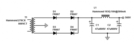
I have a 20+ WPC single ended vacuum tube stereo amp running from an Antek 360 VAC (wired for 720 VCT) toroidal power transformer. Attempts to use a vacuum tube rectifier at the power levels seen in this amp were met with sparks and dead tubes. The usual silicon diode in series with the plates and CL140 inrush limiters did not help.
I removed the UF4007 series diodes that were in series with the plates and installed the IXYS DSA1-18D diodes in their place. I saw sparks inside another 5U4, so I simply removed the rectifier tube and jumpered across it.
This leaves only the pair of IXYS diodes as the sole rectifier. This amp uses one large TV sweep tube per channel and I have operated them as high as 150 mA per tube on 470 volts. I finally settled on 120 mA which results in a B+ of 480 volts at the output tubes with a B+ current of about 250 mA.
These little diodes have proved reliable in that amp which has seen about 200 hours of use over the past 6 months. The B+ is well over the 500 volt rating on the filter caps at power on, so I have not tried to go higher.
I do have a 400 VAC power transformer that I will try with external filter caps when I have the inclination to remove the 500 volt caps from the board.....for now I would rather just listen to this one while I make another board.
These diodes should be fine for 300 VDC....their only drawback is the cost, about $3 each. Not a big deal when you only use two.
Attachments

Such a series connection without balancing resistors works fine if the reverse leakage current of the two diodes in series are equal over the entire operating temperature range. If leakage current of one diode is e.g. 10 times smaller than the other one, reverse voltages will be completely different - if we assume a linear relationship between leakage current and reverse voltage, one diode (ironically the better one) will see 90 % of the reverse voltage while the other one will only see 10% (as the current must be identical). This combination would be completely useless. Therefore a good design beeing tolerant for such mismatches uses balancing resistors. These must be designed in a way that the additional'leakage' current they will add is significantly (~10 times) higher than the max. leakage current of the diodes. If the additional current is be smaller than the leakage, the resistors would have almost no effect for voltage balancing.
- Home
- Amplifiers
- Tubes / Valves
- Rectifier diodes for tube circuits