That is very conservative rule of thumb. I am usually going around 100W per pair of to-264/to3 devices. Had no problem of pushing single pair of 2sc5200/2sa1943 to 150W per channel.Rule of thumb: single pair TO220 => 20W rms (+/-20V); single pair TO-3, TO-264, TO-247 etc. =>50W; Two pair TO-3 etc. => 100W, etc. (50W per pair)
Note that you can do better if you go class-H or class-D.
Of course, some people think constantly rebuilding amps is par for the course. Not me.
A few comercial examples:
Accuphase E480 with flimsy IRFP - rated 260W 4R - 86W per pair
Accuphase E408 with 130W transistors - rated 260W 4R - 86W per pair
Yamaha MX-A5000 with 180W devices - rated at 170W 6R , 290W single channel driven. Single pair, 11 channels, supplied with 2x72VDC.
Denon PMA amplifiers with single pair of mosfets TO3P - 2x61VDC at PSU.
Whole range of car audio amplifiers pushing easy 200W per pair (bridged, lower rails, good cooling, good protection/limiters,etc).
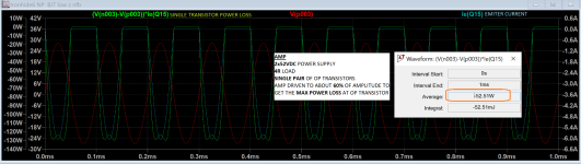
Bellow, example of power loss of single pair OPS supplied with 2x52VDC, load 4R, about 60% of output amplitude.
Regards
Attachments
100 actual watts per pair. 84 volt rails gives 250 at 8, 400 ish at 4, and 600 watts at 2 ohms on a practical power supply. Six pairs of 2N6259, MJ15024 or 21194. At “8 ohms”, it’s only 42 watts per pair, but makes a 2 ohm capable amp.
Average dissipation is only vcc^2/(10*RL) — at 60% power — but the peaks are at Vcc^2/(4*RL) when the load is resistive. Double that for a 30 degree load (at full quiescent vce). Those peaks can be longer than 10 ms, and the 100 ms SOA curve isn’t very much above the DC curve because the die makes it damn near all the way to steady state temperature by the end of 100ms.
Average dissipation is only vcc^2/(10*RL) — at 60% power — but the peaks are at Vcc^2/(4*RL) when the load is resistive. Double that for a 30 degree load (at full quiescent vce). Those peaks can be longer than 10 ms, and the 100 ms SOA curve isn’t very much above the DC curve because the die makes it damn near all the way to steady state temperature by the end of 100ms.
Bellow, example of power loss of single pair OPS supplied with 2x52VDC, load 4R, about 60% of output amplitude.
Many comercial amps do push more (sometimes much more) than 50W per 5200/1943 pair.
Average power is not really a problem. My concern is second breakdown and also the pulsed non-repetitive area when the power supply voltage is high.
Repeating pulses that exceed DC SOA or entering breakdown, even for miliseconds, may become a statistic game.
For some users, with some speakers, under certain temperature, you might have no problem.
But we never know if someone use the amp in another condition.
I prefer to be under the derated SOA DC line all the time even with reactive load.
In your example, it is exceeding the derated SOA and repeating pulses that should not be repeated..
Does this simulation considers resistive load or reactive load? I consider at least 30deg reactive load (you can model a simple woofer for that simulation with capacitor, inductors and resistance).
Look at the derated SOA below considering Tcase=80C.
6A with 24V is out of the DC line and enters in the non-repetitive area.
But audio is repetitive, so we shouldn't allow the transistor to go into that region.
Does it make sense? If not, please point it out.
This is a good discussion and I really would like to hear opinions of other people.
Guys. The rule of thumb was about amp power per package.
Exceeding SOA is a different story.
To protect SOA we have IV limiters and other protection solutions. I am using opto triac's, when excessive current occurs (just one, single shoot) the amp output is deactivated (mosfet relays) and PSU rails are turned off (eFuse).
As mentioned before example of Yamaha MX-A5000, 65V rails with single pair of OP transistors. Had one on the table few weeks back. All transistors 100% after so many years in use. It survived somehow.

My current amp (lower rails, bridged, left side of SAO chart) runs at about 125W per OP transistor (2sc5200/2sa1943) and did not managed to destroy it yet.
Ron
My example at about 60% of output amplitude (and so high rails) is extreme. Please look bellow at RMS current value (repetitive).

I think SOA charts is important (guide) but more important is real amount of energy in unit of time dissipated in transistor die which causes it to fail.
One of the key factor is cooling management and thermal resistances.
For DIY enthusiast the easiest way to determine power capabilities of OP transistor is only one way, the brake down/load test at specified cooling conditions.
My tip is, drill some 4mm/M4 holes in OP transistors, use some big washer and thin mica isolator.
There is another key factor. Important one. Not discussed too often.
How the SOA is affected by the sizing of the PSU (transformer in this case).
Please think for a moment how PSU voltage will drop under 8R,4R and 2R load with 150W transformer per OP transistor pair and 300W transformer per OP transistor pair (and determined psu caps).
Many of us, DIYers are connecting oscilloscope to the amplifier's output to do basic checks, but how many of us is connecting oscilloscope to the voltage rails while amplifier is playing some of power hungry music ?
So by sizing properly transformer we can ''adjust'' power loss and SOA region of OP trannies.
My example with 52V rails will look differed in real life than in LTSpice.
Regards
Exceeding SOA is a different story.
To protect SOA we have IV limiters and other protection solutions. I am using opto triac's, when excessive current occurs (just one, single shoot) the amp output is deactivated (mosfet relays) and PSU rails are turned off (eFuse).
As mentioned before example of Yamaha MX-A5000, 65V rails with single pair of OP transistors. Had one on the table few weeks back. All transistors 100% after so many years in use. It survived somehow.
My current amp (lower rails, bridged, left side of SAO chart) runs at about 125W per OP transistor (2sc5200/2sa1943) and did not managed to destroy it yet.
Ron
My example at about 60% of output amplitude (and so high rails) is extreme. Please look bellow at RMS current value (repetitive).
I think SOA charts is important (guide) but more important is real amount of energy in unit of time dissipated in transistor die which causes it to fail.
One of the key factor is cooling management and thermal resistances.
For DIY enthusiast the easiest way to determine power capabilities of OP transistor is only one way, the brake down/load test at specified cooling conditions.
My tip is, drill some 4mm/M4 holes in OP transistors, use some big washer and thin mica isolator.
There is another key factor. Important one. Not discussed too often.
How the SOA is affected by the sizing of the PSU (transformer in this case).
Please think for a moment how PSU voltage will drop under 8R,4R and 2R load with 150W transformer per OP transistor pair and 300W transformer per OP transistor pair (and determined psu caps).
Many of us, DIYers are connecting oscilloscope to the amplifier's output to do basic checks, but how many of us is connecting oscilloscope to the voltage rails while amplifier is playing some of power hungry music ?
So by sizing properly transformer we can ''adjust'' power loss and SOA region of OP trannies.
My example with 52V rails will look differed in real life than in LTSpice.
Regards
Hi! Ok, if you keep the operation under the thermal derated single pulse SOA and remove power right after the first shot maximum allowed time, that's fine.To protect SOA we have IV limiters and other protection solutions. I am using opto triac's, when excessive current occurs (just one, single shoot) the amp output is deactivated (mosfet relays) and PSU rails are turned off (eFuse).
If you shutdown electronically there is enough time (10 to 100ms).
Let's consider your example 125W per pair and case temperature Tc=80C, so heatsink around 60 to 70C.My current amp (lower rails, bridged, left side of SAO chart) runs at about 125W per OP transistor (2sc5200/2sa1943) and did not managed to destroy it yet.
With 4ohm load, we need 22.4VRMS or 32Vpeak in the output. Let's allow 3V loss between output and power supply rail, so 35V on power supply under load. Let's consider 18% drop from power supply unloaded to loaded, so this would need a +/-42VDC rails.
With resistive load, worst SOA scenario is 35/2=> VCE=17.5V and 17.5/4=> Ic=4.3A
It gets very close to the DC line, so it would be fine. You can operate it for hours, days continuously.
But, with a reactive load of 30deg, the SOA scenario is VCE=27V with Ic=4.9A.
In this case case, you get close to the 100ms line, so you really need a single shot fast shutdown.
As we can see, if pushing 125W per 5200/1943 pair, you do need special protection for normal operation - we are not even talking about short circuit condition or some speaker impedance drop below 4ohm along the frequency range, which can happen sometimes (3.5, 3.3 in some frequencies - it will depend on the speaker designer). Normally some margin is needed.
That Yamaha with rails of +/-65V (no load) is still risky.
The 2SC5949 / 2SA2121 pair is more robust than the 2sc5200/2sa1943.
The 2SC5949 / 2SA2121 derated to Tc=80C can handle 125W (DC) while the 2sc5200/2sa1943 can handle only 84W (DC).
Let's consider same 18% drop. 65*0.82=53V. Consider 3V drop, we get 50Vpeak at the output. This gives us 50*0.7=35VRMS.
Over 4ohms, we get 35^2/4=306W. A lot of power for a single pair.
50/2=> VCE=25V and 25/4=> Ic=6.2A. It exceeds the DC SOA region. And with reactive load, it will exceed much more.
And this is considering Tj=150C. I normally design to around Tj=130C wosrt scenario.
I know I'm considering extreme cases with constant sinewave load at the worst frequency scenario.
The reactive load worst scenarios occur in some frequencies only, so when listening to music, the amp will just pass by them and not always with exaclty worst SOA case.
But we have to keep in mind when we are listening to music, we are on the statistic territory. If the amp owner decides to listen to some strange music or measure power with a sinewave at a frequency where the load phase is 30deg, there will be repetitive SOA incursions and fast protection needs to kick in.
That conservative rule of thumb, as all rules of thumbs, get us out of all this milimetric calculations and out of the statistics considerations.
For me the SOA is the upper limit (a roof) that must be checked and with simulation tools is so easy - I normally simulate the transformer separately (using primary/secondary resistances) and rectifier (diodes+caps) to check how much drop I will have. Then I simulate the amp with unload and load voltages to see the scenarios. I also use a reactive load in simulation - a simple set of components to mimic the speaker impedance.
In my case, since I LOVE these measurements and calculations 🙂love🙂, when the amp PCB is ready, I do measure all these milimetric voltages and currents to make sure it is working as simulated. That's the fun part of the amps for me.
In summary, what upsets me is that a lot of amp vendors design the circuit and let the transistor exceed the SOA, for miliseconds, I know, but the datasheet is very clear that these 100ms, 10ms, 1ms SOA regions are for non repetitive pulses. But audio is repetitive.
It's a different story with MOSFET's, for which we have a chart showing us the repetitive SOA area (beyond the DC area) we can use as a functiona of pulse duration and duty cycle.
MOSFET's don't have the avalanche effect that BJT has, so current density in MOSFET in its die is more uniform as opposed in the BJT, where hotspots are easily created and lead to failure.
Old school data sheets specified that repetitive operation is ok provided that max Tj is not exceeded. The thermally limited portion of the curve (slope =-1) under pulse conditions indicated the dissipation level where a single pulse would reach 200C. Obviously, that de-rates with temperature, putting the thermal limit somewhere between the DC curve and the “single pulse”. As you go higher in temp, the thermal limit line keeps coming down, eventually overtaking the second breakdown limit.
Attachments
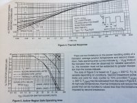
Yes. If the transitor datasheet gives us data for calculating the repetitive region above DC, I'm safe to operate on that.Old school data sheets specified that repetitive operation is ok provided that max Tj is not exceeded. The thermally limited portion of the curve (slope =-1) under pulse conditions indicated the dissipation level where a single pulse would reach 200C. Obviously, that de-rates with temperature, putting the thermal limit somewhere between the DC curve and the “single pulse”. As you go higher in temp, the thermal limit line keeps coming down, eventually overtaking the second breakdown limit.
I already build some switching mode power supplies using this region - most MOSFET datasheets have this information.
My concern is that when we are using a BJT, such as 2sc5200/2sa1943, whose datasheet clearly states that the regions above DC are for single pulse only.

I 2nd the MJL3281, excellent for a SE follower design.MJL3281/MJL1302
2SC5200/2SA1943
On paper, 2SC5200/2SA1943 is easier to drive comparing to MJL3281/MJL1302, due to lower Cob.
Ok! Got you point. In fact, every BJT has a repetitive region above the DC, but we need to know the device's dynamic thermal behavior in order to define the duty cycle that allows a certain incursion above DC line.Those single pulse curves just show where the single pulse hits 150C. If you HAD the transient Rth data (like in the 2N5631 data sheet) one could calculate for any duty cycle. They don’t seem to publish this anymore.
What happens with the 2sc5200/2sa1943 is that they don't publish this data or no longer publish it.
Thank you, it makes total sense!
- Home
- Amplifiers
- Solid State
- Recommendations for output transistors?