
I called it 'mini F5-Juma' but it's a mix of F5, VSSA I believe...not too sure but it does sound very nice.
VSSA uses MOSFETs at output as Source followers and BJTs as VAS which was Fab's idea years before VSSA and I used BJTs at the input of F5 also before VSSA so this amp is just a small, single rail, BJT+LAT version of F5...
I guess it fulfills the post #1 requirement - to sound different from ACA. 🙂
I guess it fulfills the post #1 requirement - to sound different from ACA. 🙂
Of course it does fulfill post no.1 !!
I got mixed up because the VSSA I recently bought from Jason (TO-3 version) is intended to work with LatMOS, not vertical.
Thanks
Eric
I got mixed up because the VSSA I recently bought from Jason (TO-3 version) is intended to work with LatMOS, not vertical.
Thanks
Eric
Last edited:
Sorry, I forgot it is a common source design. You are correct.+24 V and GND are connected to Source (center pin), identical to Juma scheme
Is not that correct?
Fab
Sorry, I forgot it is a common source design. You are correct.
Fab
No problems ....
Adding a volume ctrl.
Hi,
If I want to add a volume control, which value do I choose and is my volume located properly on my schematic ? I have chosen 20K but is this a good value, I haven't bought the pot yet. My source will be either a CD player or the output of a future DAC.
How do you choose between, 10K, 20K or 50K. Just want to make sure my chosen value is OK and won't affect the bandwidth and overall gain.
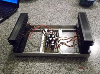
p.s. Pic of the amp being built.
Thanks,
Eric
Hi,
If I want to add a volume control, which value do I choose and is my volume located properly on my schematic ? I have chosen 20K but is this a good value, I haven't bought the pot yet. My source will be either a CD player or the output of a future DAC.
How do you choose between, 10K, 20K or 50K. Just want to make sure my chosen value is OK and won't affect the bandwidth and overall gain.
p.s. Pic of the amp being built.
Thanks,
Eric
Attachments
Last edited:
Chassis design looks nice and sturdy. A metal bottom and top plates bolted to the heatsinks should help remove a bit more heat.
The volume control placement on the schematic looks ok to me. Considering your sources are CD player and DAC with usually lower than 1K output impedance, I would say your 20K choice is also acceptable. Juma however has more listening hours on this ckt type.
The volume control placement on the schematic looks ok to me. Considering your sources are CD player and DAC with usually lower than 1K output impedance, I would say your 20K choice is also acceptable. Juma however has more listening hours on this ckt type.
...How do you choose between, 10K, 20K or 50K...
We choose the pot value by two criteria:
- as high as possible to avoid overloading the previous stage
- as low as possible to avoid creating a strong low-pass filter that series pot resistance makes with the input capacitance of the next stage
Sensible compromise between these two contradicting demands is a 10k pot. Any previous stage that can't handle 10k load needs a buffer anyway because it won't be able to properly drive the cable capacitance either.
10k pot puts maximally 2k5 series resistance in the line which won't build very strong LP filter with typical input capacitance of pre/amp.
If you already have a good 20k pot it's OK to use it with this amp.
However, my experience is that amps with BJT input stage sound better with a buffer (B1 or similar) between the pot and the amp's input. You might come to different conclusion, since this amp's input BJTs work with low Ib (5-6uA). Anyway, it's easy to test it...
Last edited:
I generally buffer my volume potentiometer.
This allows me to use any value from 10k pot to 1M pot.
If you don't intend buffering the vol pot output then:
1.) you must make allowance for cable and receiver capacitance. The vol pot MUST be able to drive that capacitance.
2.) the maximum output impedance (Ro) of the vol pot will interact with the receiver input impedance (Rin). Aim for a ratio {Vol Pot Ro} : {Receiver Rin} < 1:10 and preferably <1:20
To assist with meeting those two conditional requirements, I suggest you adopt ~10k vol pot.
10K it is then. Thanks to all for the explanation.
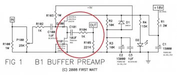
Question : If I was going to insert the B1 in there what JFET could I use instead of 2SK170, LSK170 or 2SK370...these seems to be very hard to get, is there any new component that are easier to buy (buying 2SK170 now is risky, I like genuine stuff)
Would I only need to add the 5 circled components to buffer my volume, the rest seems to be already in the amp ?
Eric
Attachments
Last edited:
Grade A (Idss 2.6 - 6.5): 8 pieces $17.68 ($2.21 each)
Grade B (Idss 6 - 12): 8 pieces $16.72 ($2.09 each)
Grade C (Idss 10 - 20): 8 pieces $15.76 ($1.97 each)
Grade D (Idss 18 - 30): 8 pieces $15.76 ($1.97 each)
B
...Would I only need ...
I would save that for later. Right now it would be OK to test the 10k pot at the amp's input (I suppose you want your pot inside the amp, without long cables between the pot and the amp) and if you have no complaints, the buffer might not be needed...
Juma has given details of a bf862 version of a buffer that is almost identical to the B1.
A jFET source follower with jFET CCS load.
A jFET source follower with jFET CCS load.
Got the new amp connected to my FE206E, sound is simply GREAT to my ears.
Thanks for the amp design and PCB layout.
BR,
Eric
Thanks for the amp design and PCB layout.
BR,
Eric
- Home
- Amplifiers
- Pass Labs
- Recommendation for 5-10W amp.