So, is RCA's 7027A the same tube as the GE 7581A?
Regarding the RCA paper from #3: This is an amazing document, thanks for it! It makes me scratching my head, tjough: How could RCA claim those quite sophisticated performance data without even specifying the output transformers as the amplifiers' cores?
Best regards!
Regarding the RCA paper from #3: This is an amazing document, thanks for it! It makes me scratching my head, tjough: How could RCA claim those quite sophisticated performance data without even specifying the output transformers as the amplifiers' cores?
Best regards!

To the best of my understanding, close enough to swap 'em -- IF you take care of differences in their pinouts.So, is RCA's 7027A the same tube as the GE 7581A?
There are slight differences in pinouts to look out for.
The basing for 6L6GC:
The basing for 7581A is 7AC and looks identical to 6L6GC:
The basing for 7027A has pin 1 internally connected to G2, the screen grid. It also has pin 6 internally connected to G1, the control grid. Those are differences you will need to account for.
--
Last edited:
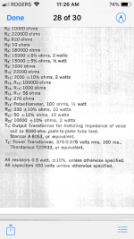
Thanks, I missed that 🙄!Actually each output transformers is specified on the page following each schematic, it’s in the BOM. Pic attached is for the 30W
BR
Eric
Are there any datasheets for the recommended OT's?
Best regards!
Well, I got a nice surprise this morning, while looking for something in the garage I found a KT88 quad I had purchased a few years back. Based on the spec sheet it looks like it will fit like a glove for my 30W per channel. See pic
So unless someone says it doesn’t make sense there will be my output tube.
Will the 6GH8 have enough drive?
Thanks
Eric
So unless someone says it doesn’t make sense there will be my output tube.
Will the 6GH8 have enough drive?
Thanks
Eric
Attachments
Nice find.
I ordered a quad of KT-88s from Eurotubes which made it across the border to Canada and the local sorting depot and has since disappeared. I'm hoping it's just a mixup and not a theft.
I ordered a quad of KT-88s from Eurotubes which made it across the border to Canada and the local sorting depot and has since disappeared. I'm hoping it's just a mixup and not a theft.
I guess you have a tracking number. If you paid with a credit card you should be ok, most come with insurance.
Well, I got a nice surprise this morning, while looking for something in the garage I found a KT88 quad I had purchased a few years back. Based on the spec sheet it looks like it will fit like a glove for my 30W per channel. See pic
So unless someone says it doesn’t make sense there will be my output tube.
Will the 6GH8 have enough drive?
Thanks
Eric
KT88 should work nicely. However, when you look for the power transformer you'll need to take make sure it delivers enough current for both the heater and the plate supplies.
The KT88 heater requires 6.3V 1.5A per tube, so 6A of heater power is required just for the four output tubes. You'll need another 1A for the driver tubes, so the heater winding will need to deliver at least 7A. That might not be easy to find.
For comparison, 7027A heater uses 6.3V 0.9A. Four of them require 3.6A instead of 6A. That's a big difference.
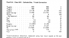
Also, in most designs, KT88 will be used at higher plate currents than 7027A. The chart you posted earlier shows the KT88-triodes run with 76mA plate current per tube. with 349V plate-cathode. The quiescent plate current will be over 300mA for a stereo amp, and you'll want the power transformer to deliver more than that to deal with high power transients (like bass drum thwacks and music with a lot of low bass).
I'd say you'd be best off building mono-blocks, so each side can use a 200mA rated power transformer with a 4A (or better) heater winding. Incidentally, that's the current required for four EL84 tubes (for a stereo amp). KT88 is a good tube, but it's a power-hungry beast.
Thanks I’ll look into this. I had already thought of buying a separate 6.3V just to power the heaters. Hammond has plenty.
I had kept these KT88 for a more powerful amp (2 mono), something like 50W, I already have a huge PT and OPT for it but I figured I could use them now until I have the moula to buy a decent set of output tubes. I hadn’t bought output tubes for a while, I’ve been focusing lately on some SS Pass amps. I’ll probably buy a quad of KT77 instead of 6P3S-e. I’ve read many times that KT77 are great for classic rock (my cup of tea..)
Thanks
Eric
One thing to take note of is that the 30 watt amplifier in the RCA tube brochure uses fixed bias for the output tubes, and this bias is not adjustable in the circuit as published. The bias circuit is a bit unusual in that it is not derived from a separate transformer winding or a "bias tap" on the main secondary winding. The (negative) bias voltage is developed across R20 in the schematic, which is valued at 220 ohms (10 watts), and this resistor value will probably need to change if you change output tubes. I noticed that the RCA Receiving Tube Manual contains the same circuit but uses the 7868 output tube instead of the 7027, and its value for R20 is 120 ohms, rather than the 220 ohms used with the 7027. There are also some other component value differences but these don't affect the operation of the output stage. The power transformer specified is the same in both versions of the RCA 30 watt amplifier.
I won't try to guess at what an appropriate value would be for R20 using the KT88 output tube in your build because that value will depend not only on the particular output tube chosen but also the B+ voltage applied to the output stage, which in turn depends on the specifications of the power transformer you end up using. So be prepared to do some experimentation to set the output tube bias at an appropriate level for whatever output tube and power transformer combination you select.
I won't try to guess at what an appropriate value would be for R20 using the KT88 output tube in your build because that value will depend not only on the particular output tube chosen but also the B+ voltage applied to the output stage, which in turn depends on the specifications of the power transformer you end up using. So be prepared to do some experimentation to set the output tube bias at an appropriate level for whatever output tube and power transformer combination you select.
Thank you very much Ray.
I did noticed an odd way of wiring the fixed bias. I’ll go the traditional way instead.
Eric
I did noticed an odd way of wiring the fixed bias. I’ll go the traditional way instead.
Eric
Well-spotted. However this is not "fixed" bias. Voltage developed is according to current drain.The 30 watt amplifier in the RCA tube brochure uses fixed bias for the output tubes, and this bias is not adjustable in the circuit as published. The bias circuit is a bit unusual in that it is not derived from a separate transformer winding or a "bias tap" on the main secondary winding. The (negative) bias voltage is developed across R20
In a radio with a bunch of RF/IF tubes this was called "back bias". Variation of current in output, or tuner, were diluted by being summed with all the other current.
In this case the 7199 only draws maybe 8mA, while the 7027s suck 120mA, so it is 94% Cathode Bias.
Which is not a surprise. The 30W (design Max) 7027 can theoretically deliver 30W/pair in class A, and self-bias is very much more forgiving of tube and circuit tolerances.
FWIW, book value for 32W 400V 6600r is 200 Ohms. 220r may just be nearest standard value.
Use the datasheet number for that B+ and load. If "all" the current flows through, go down maybe 5% to cover preamp/driver current.guess at what an appropriate value would be for R20 using the KT88
Part of the "magic" of cathode bias is that largeish variation of cathode resistor makes a smaller variation in tube current.
The attached schematic is the non-NFB PP amp that me and my buddy built. I changed the input stage to 6J5 with cathode resistor of 820 ohm. Power tube can be EL34 or KT66. With KT66, the output power is 23 watts at 5% in ultra linear mode. With EL34, it is better to run it in Triode mode for lower distortion.
Johnny
Johnny
Attachments
Using an old console's existing power transformer and original output transformers can limit what you can do in terms of a new amplifier design.
1. Power transformer's maximum load current for Cap input filter; or Choke input filter.
Power transformer's maximum filament current
2. Output transformer's maximum quiescent current
Output transformer's maximum un-balanced quiescent current
Output transformer's primary impedance
Output transformer's maximum low distortion power, especially at bass frequencies, but also at mid band and high frequency
Output transformer's Frequency response & phase response
Versus:
3. The choice of output tubes; output mode (beam power/pentode), ultra linear (if there is a UL tap), or triode/triode wired mode.
No negative feedback; negative feedback: Global, Schade, Cathode, etc., or a combination of 2 or more of those.
4. The number of combinations that will work are almost infinite.
Warning, the combinations that will NOT work are also almost infinite.
. . . Attention to details is necessary to make a Well Working, good sounding, And Reliable amplifier.
Just my experience and my opinions
I already have new PT and OPT but that can be boring.
I simply wanted to save this power amp from going into the waste field, it’s also more challenging than buying exactly what is needed in a new design.
The fun factor is much higher with these old console stuff and often you find some unsuspected gems 👍
Keep on building.
I simply wanted to save this power amp from going into the waste field, it’s also more challenging than buying exactly what is needed in a new design.
The fun factor is much higher with these old console stuff and often you find some unsuspected gems 👍
Keep on building.
You are technically correct, of course. I was just trying to point out that the published bias scheme is non-adjustable and probably won't work with the OP's build without modifications. There is certainly more to this build than just changing output tubes. 😉Well-spotted. However this is not "fixed" bias. Voltage developed is according to current drain.
In a radio with a bunch of RF/IF tubes this was called "back bias". Variation of current in output, or tuner, were diluted by being summed with all the other current.
Several times I have taken an existing amplifier, and then taken everything off of it.
I re-use the chassis (aluminum please, not magnetic steel), and the power transformer, that is all.
But first . . . I find out what the B+ secondary voltage is, rectifier is - tube type number, or solid state rectifiers; filter: cap input or choke input; B+ current draw is versus input filter, and the filament current draw.
Then I begin to look at it in a way that is completely different than the original amplifier . . .
I decide on something I would like to design, build, and like to listen to, that uses the original chassis and power transformer.
These are often lower power than the original amplifier, but I do not need very much power.
But I do take a conservative approach when I design the power supply, with lighter than original loads on the power transformer. Less filament current, and choke input filter is about 90% of how to achieve that goal . . . Cool and reliable.
I could use tube or solid state rectification; a choke input or cap input B+ filter; push pull output, single ended output, with output triode, beam power, or pentode tube(s); Ultra Linear, Beam Power / Pentode, or Triode/Triode wired output(s). It could be a mono-block or stereo.
Then there is the design of input stage, driver, phase splitter, just one of those depending on the rest of the amplifier.
The only negative feedback I use is either triode/triode wired, or Ultra Linear.
Diamond cutters look at the raw stone first, and visualize. Then they cut. Profit.
I do something similar, but not to bring any profit.
Anybody that wants to take a console, and re-use the same parts to make a more powerful amplifier has to do two things . . . make both the output stage and the power supply more efficient.
Failure to to that will end up in Smoke.
It is so hard to stuff the smoke back in, after it gets out.
Last edited:
- Home
- Amplifiers
- Tubes / Valves
- Recommandation for PP about 30-40W with 4K OPT w/o UL.