Thank you very much, Mooly, for studying the schematic in detail. I am changing all the electrolytic capacitors, so the faulty capacitor will be replaced.
I have already removed them, so I will measure the voltage of R553 later on.
My question is probably silly: does the "15V" written next to D50 mean that 15V must be measured here? Or does it mean that it is a 15V Zener diode? As mentioned above, I have an 18V Zener diode on my circuit board.
I have already removed them, so I will measure the voltage of R553 later on.
My question is probably silly: does the "15V" written next to D50 mean that 15V must be measured here? Or does it mean that it is a 15V Zener diode? As mentioned above, I have an 18V Zener diode on my circuit board.
I would take it to mean a 15 volt Zener but its function is to limit the voltage on Q51 collector. It looks non critical and if 18 volt is fitted then that would be fine also. If the high voltage unregulated supply is present on those 680 ohm resistors then I would expect to see 15 or 18 volt across the Zener.
Hi,
https://www.diyaudio.com/community/...=372355&hash=d3c9eb6ea57310e857cdc34c42ff5e26
I have successfully changed all electrolytics and replaced the damaged resistors and diode on one channel. Half of the capacitors were faulty (wrong value or high resistance). I could test the amp, which seems to work fine now.
Thank you for your advice which allowed me to reach this first stage!
I decided to go for the second channel. Unfortunately, I broke one power transistor (Q19) while trying to remove it from the radiator (as explained above).
It is not a big deal to find some stocks of MJL1302A on eBay. However:
- Do you confirm that I absolutely must replace it?
- If so, can I replace this one (Q19) only ? Or should I pair it with Q15? And how can I pair those two?
Attachments
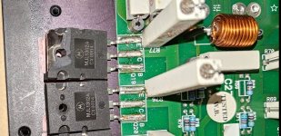

The die on MJL1302 is not near the corner that broke off. I would leave it. Output transistors need to be matched for Vbe or gain, so all of the ones in parallel gets you a chance of a better match.
While a buy a lot of things on e-bay, transistors is not one of them. Many chances of counterfeits. I buy transistors and electrolytic caps from authorized distributors like Farnell, Digikey, Mouser, RS of the UK, Reichelt of Germany. You will pay freight, and customs from the UK.
While a buy a lot of things on e-bay, transistors is not one of them. Many chances of counterfeits. I buy transistors and electrolytic caps from authorized distributors like Farnell, Digikey, Mouser, RS of the UK, Reichelt of Germany. You will pay freight, and customs from the UK.
As a general rule don't even think of buying semiconductors off eBay, far far to many fakes and remarked parts around. Always buy parts from authorised dealers.t is not a big deal to find some stocks of MJL1302A on eBay0
Agreed although it looks like it not be able to be torqued down correctly as the face is uneven.The die on MJL1302 is not near the corner that broke off. I would leave it.
Q15? I see Q19 as its paralleled pair. They should ideally be at least from the same batch. The emitter resistors will do the rest as far as matching goes.If so, can I replace this one (Q19) only ? Or should I pair it with Q15? And how can I pair those two?
Thank you to both of you. I chose to keep the transistor as it was, since the broken piece could easily be put back and the transistor correctly torqued.Agreed although it looks like it not be able to be torqued down correctly as the face is uneven.The die on MJL1302 is not near the corner that broke off. I would leave it.
I'm now done with the recapping. I was able to test the amp on some cheap speakers. It is working so far. I can measure a residual voltage of 0.009 V on the left channel and -0.056 V on the right. Are these values acceptable, or should I adjust something?
Is there any check you would suggest before testing it on my KEF 105/3?
Perfectly acceptable and they probably drift with temperature anyway. -/+100mv was a widely accepted figure years ago. Work out the power dissipated and current flowing in an 8 ohm load caused by 100mv and you will see its a non issue.Are these values acceptable, or should I adjust something?
I was able to set the two channels to 0V after the amp ran for several hours. I warmly thank all of you who answered my stupid questions. Let's see if what I did is sustainable over time.There`s one multiturn potmeter on each channel. That is for adjusting DC offset. Amp should be warm first. Adjist for as close to 0VDC as you can.
R
For now, I must say that I am fully satisfied with the sound of the amp. I can compare it to a Quad 405. The Meridian sounds more dynamic and more neutral, whereas the Quad sounds more plain but maybe a bit boomy.
- Home
- Amplifiers
- Solid State
- Recapping Meridian 557