Hello, everybody,
I have recently acquired a Harman Kardon Citation 16 series A from the well-known auction site. The amp was said to be "tested and have no issues with the sound." Wanting the amp really badly (out of curiosity and nostalgia), I overspent a bit to get it.
Upon arrival, I did some readings of DC offset and all was not well... The right channel was fine -- about 25mv before any adjustments. However, the left channel had nearly 1.0 volt of DC at the outputs. Also, the idling current was very high on this channel (the tech manual says there should be 50mv DC across one of the emitter resistors, and in this channel it was around 140mv).
It looked like the amp had some work done on it before I acquired it as well (different input coupling capacitors, and one different power capacitors -- both on the faulty channel).
Not wanting to deal with returning it and knowing I would have to rebuild/recap it anyway, I proceeded to carefully perform a recap of all the electrolytic capacitors (including the power supply caps), and replaced components that are notorious for going out of spec (the 2W 3900 ohm power dropping resistors on the driver board were about 20% off on the bad channel (in both directions!); and I replaced all the zener diodes with 2% tolerance units).
The variable resistors that are used to adjust bias and DC offset are also notoriously bad, so I replaced them with 15-turn pots that are more precise.
NOW, things are better, but not right.
I can now get DC offset in *both* channels to 1.0mv, no problem.
However, the originally (and still) problematic L channel has no bias current. Tech manual says there should be 50mv across the an emitter resistor on the output transistors. Now there is around 1 mv.... And, adjusting the bias control pot (VR2) does something very strange. For most of the adjustment, bias stays at around 1 - 2mv until one very specific point where it jumps to -1.3v (!!!) ... There is no in-between. Obviously I didn't keep the setting here very long. However, upon a short test (very low bias) with music...this channel sounds like pure crossover distortion (quite awful). Other channel is great.
Attached are the schematics. There are two darlington transistors in the bias circuit -- Q11 and Q18. Could one of those be bad? I know the variable resistor is fine, as I tested it (and even put the stock pot back in with the same result).
I have limited knowledge of circuit design, so any help you guys could provide would be great. Thanks in advance!! I really want to get this thing working after the investment I put into it.
I have double checked my work several times and don't see anything stupid I have done (though I have missed dumb mistakes in the past...)
Thanks again.
I have recently acquired a Harman Kardon Citation 16 series A from the well-known auction site. The amp was said to be "tested and have no issues with the sound." Wanting the amp really badly (out of curiosity and nostalgia), I overspent a bit to get it.
Upon arrival, I did some readings of DC offset and all was not well... The right channel was fine -- about 25mv before any adjustments. However, the left channel had nearly 1.0 volt of DC at the outputs. Also, the idling current was very high on this channel (the tech manual says there should be 50mv DC across one of the emitter resistors, and in this channel it was around 140mv).
It looked like the amp had some work done on it before I acquired it as well (different input coupling capacitors, and one different power capacitors -- both on the faulty channel).
Not wanting to deal with returning it and knowing I would have to rebuild/recap it anyway, I proceeded to carefully perform a recap of all the electrolytic capacitors (including the power supply caps), and replaced components that are notorious for going out of spec (the 2W 3900 ohm power dropping resistors on the driver board were about 20% off on the bad channel (in both directions!); and I replaced all the zener diodes with 2% tolerance units).
The variable resistors that are used to adjust bias and DC offset are also notoriously bad, so I replaced them with 15-turn pots that are more precise.
NOW, things are better, but not right.
I can now get DC offset in *both* channels to 1.0mv, no problem.
However, the originally (and still) problematic L channel has no bias current. Tech manual says there should be 50mv across the an emitter resistor on the output transistors. Now there is around 1 mv.... And, adjusting the bias control pot (VR2) does something very strange. For most of the adjustment, bias stays at around 1 - 2mv until one very specific point where it jumps to -1.3v (!!!) ... There is no in-between. Obviously I didn't keep the setting here very long.
However, upon a short test (very low bias) with music...this channel sounds like pure crossover distortion (quite awful). Other channel is great.Attached are the schematics. There are two darlington transistors in the bias circuit -- Q11 and Q18. Could one of those be bad? I know the variable resistor is fine, as I tested it (and even put the stock pot back in with the same result).
I have limited knowledge of circuit design, so any help you guys could provide would be great. Thanks in advance!! I really want to get this thing working after the investment I put into it.
I have double checked my work several times and don't see anything stupid I have done (though I have missed dumb mistakes in the past...)
Thanks again.
Attachments
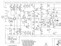

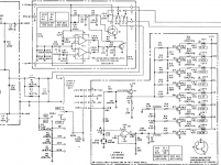
Measure the DC voltage between the collectors of Q15 and Q17 as you turn the pot. The voltage should rise smoothly.
Do you have a scope ? The problem could be a symptom of instability. Monitoring the output would be a first basic test really to confirm (or not) whether this was an issue.
Does the offset vary as the bias is altered ? It should not.
Do you have a scope ? The problem could be a symptom of instability. Monitoring the output would be a first basic test really to confirm (or not) whether this was an issue.
Does the offset vary as the bias is altered ? It should not.
Hi Mooly.
Thanks for the fast response.
DC voltage between the collectors of Q15 and Q17 is about 3.05 VDC. As I turn the pot, it rises and lowers smoothly, but the change is not great at all -- about .05 volts per turn.
I don't have scope, unfortunately.
Thanks for the fast response.
DC voltage between the collectors of Q15 and Q17 is about 3.05 VDC. As I turn the pot, it rises and lowers smoothly, but the change is not great at all -- about .05 volts per turn.
I don't have scope, unfortunately.
Once you have reduced the bias to the correct voltage, R19 will tweak the offset. Try and get the offset to 0v plus or minus 10mV.
Offset is about 1.0mv in both channels.
The bias won't adjust properly in the bad channel. Either the reading across the output emitter resistor is 1-2mv or around -1.3 volts. It doesn't adjust smoothly, but just changes immediately at a certain point.
The bias won't adjust properly in the bad channel. Either the reading across the output emitter resistor is 1-2mv or around -1.3 volts. It doesn't adjust smoothly, but just changes immediately at a certain point.
A scope would be useful... however...
You need to be very careful working on this. Normally we would advise using a bulb tester to limit current in the event of a problem.
I'll take a closer look later 🙂 In the meantime you could compare the reading between collectors of the good channel vs the bad. You need to overcome all the base-emitter voltdrops before the output stage begins to conduct. That puts the bias voltage (between those collectors) at around 3.5 volts before things start to happen.
My worry is its unstable. Basic checks for now are to make sure that all those 0.5 ohm resistors are OK and the 5.6 ohms. Make sure all the small value caps are correct in value (as you say the amp has been worked on). That's all the pf and nf values.
Sure. I actually just compared them!
In the bad channel, the voltage between the collectors is about 3.05VDC. In the good channel, the voltage is about 3.75VDC.
I have a bulb tester. Maybe I should use it...
I don't think any of the small-value caps were changed -- they all appear to be stock, but I will check what you are recommending!
Thanks for your help!
I believe all the transistors in the output section are original. I will check in a bit. All the transistors on the driver boards are originals.
One thing you could try as an experiment.
If its oscillating at hf then we might be able to detect it by you adding a small series network of a resistor (say 1K), a diode (such as a 1n4148) and a cap (say 0.1uf) connected from the output (use the true amp output to the left of L1) and ground. Have the cap at the ground end of the chain and measure the DC voltage across the cap as the pot is turned. If voltage appears suddenly (providing the offset is still zero) then you have oscillation.
If its oscillating at hf then we might be able to detect it by you adding a small series network of a resistor (say 1K), a diode (such as a 1n4148) and a cap (say 0.1uf) connected from the output (use the true amp output to the left of L1) and ground. Have the cap at the ground end of the chain and measure the DC voltage across the cap as the pot is turned. If voltage appears suddenly (providing the offset is still zero) then you have oscillation.
I will have to try this in a bit. I have no spare diodes laying around (besides zener).
Do you think possible oscillation would be the cause of no bias voltage? In the mean time, I will check the resistors on the heat sink.
Do you think possible oscillation would be the cause of no bias voltage? In the mean time, I will check the resistors on the heat sink.
One more little tidbit of information:
The heatsinks on the bad channel didn't get warm at all, even after being on for several minutes.
I just got done removing all of the output transistors so I can check the resistors. They are all original RCA components.
The heatsinks on the bad channel didn't get warm at all, even after being on for several minutes.
I just got done removing all of the output transistors so I can check the resistors. They are all original RCA components.
Did a rudimentary test (using a multimeter) of all the output devices in the bad channel, and nothing seemed out of the ordinary. Nothing shorted, atleast.
Guess I scared everyone off. 😉
I found something odd that may be relevant in the problem.
R32, which is in the biasing circuit, is listed on the schematic as being a 680 ohm resistor. However, a 470 ohm resistor is in its place. Unfortunately, the working channel also has a 470 ohm resistor in place of the 680...but do you think that would throw something sufficiently off kilter to mess up the bias current?
One more little tidbit of information:
The heatsinks on the bad channel didn't get warm at all, even after being on for several minutes.
I just got done removing all of the output transistors so I can check the resistors. They are all original RCA components.
They wouldn't get warm at the minimum bias level but they would (or should) at the level you say the bias jumps to. Not just warm but hot, and very quickly.
All the 0.5 ohm emitter resistors test fine as do the 5.6 ohm resistors.
Good
Did a rudimentary test (using a multimeter) of all the output devices in the bad channel, and nothing seemed out of the ordinary. Nothing shorted, atleast.
Good
Guess I scared everyone off. 😉
I found something odd that may be relevant in the problem.
R32, which is in the biasing circuit, is listed on the schematic as being a 680 ohm resistor. However, a 470 ohm resistor is in its place. Unfortunately, the working channel also has a 470 ohm resistor in place of the 680...but do you think that would throw something sufficiently off kilter to mess up the bias current?
Not really 🙂 It was getting late here 😀
The 680 to 470 ohm is typical of a production change, nothing to worry about.
The more I think on this and the more it sounds like instability. The other big worry is that the faulty channel has been worked on before and so anything is possible.
As you turn the bias pot you all you are doing is allowing a steady DC voltage to develop across the output and driver stages thus turning them on. It should be a slow and steady increase and at the point at which the output stage begins to conduct, well the current flowing in the output transistors should also increase slowly from that point on. A sudden jump is absolutely typical of a stage that bursts into oscillation as it comes into conduction.
As you turn the bias pot you all you are doing is allowing a steady DC voltage to develop across the output and driver stages thus turning them on. It should be a slow and steady increase and at the point at which the output stage begins to conduct, well the current flowing in the output transistors should also increase slowly from that point on. A sudden jump is absolutely typical of a stage that bursts into oscillation as it comes into conduction.
Damn. That's not good.
You are right -- when the voltage jumped to -1.3vdc, the heat sink got hot very quickly -- I didn't leave it there very long, obviously. Before the recap job (and when the DC offset on that channel was around 1 volt), the bias current was high (140mv), but stable -- so obviously I did something to make it worse...
What you say about oscillation makes perfect sense and fits the description of the problem. What causes this oscillation and is there a way I can combat it?
Thanks for your help and expertise.
How determined are you to have a go at this ?
Without a scope its all a lot more difficult but it might still be do-able. It involves quite a lot of basic checks... and no absolute guarantee of fixing it... but there is a fair to good chance.
Without a scope its all a lot more difficult but it might still be do-able. It involves quite a lot of basic checks... and no absolute guarantee of fixing it... but there is a fair to good chance.
- Home
- Amplifiers
- Solid State
- Rebuilding Harman Kardon Citation 16A! Please help!!