OK then, I'll take a look at the circuit and see what I can come up with. A lot of the stuff to check will seem basic and perhaps unnecessary but it all has to be covered. Depending on the outcome of that we can possibly look at running the amp without the full output stage and drivers.
Thanks! I'll look forward to the tests you come up with. Hopefully I will be able to try them in the next few days!
Again, thanks for your time and help.
Again, thanks for your time and help.
As the amp has been worked on you need to confirm the following,
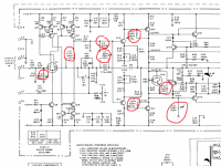
1. That the caps marked in red are fitted correctly and have the correct values. Also make sure that the print they connect to goes to where it should (no breaks or hairline cracks).
Also check that C1 (0.1uf on the speaker output side of L1 is present and correct.
2. Confirm all the transistors are the correct type. Have any been replaced ?
3. Confirm that the voltage across the four zeners CR3, CR4, CR5 and CR6 are as marked within 20%
4. Confirm there is around 0.7 volts across R5
That's probably plenty to start with... and we have to start somewhere 🙂
Attachments
As the amp has been worked on you need to confirm the following,
1. That the caps marked in red are fitted correctly and have the correct values. Also make sure that the print they connect to goes to where it should (no breaks or hairline cracks).
Also check that C1 (0.1uf on the speaker output side of L1 is present and correct.
The ceramic caps on the driver board are all the correct value (and appear to be stock). The traces on the circuit board seem to be fine and pass continuity tests.
2. Confirm all the transistors are the correct type. Have any been replaced ?
All the output transistors on the heat sink are original RCA's with matching codes. Q1 and Q2 on the heat sink also match. I am unsure about the transistors on the driver board, but they appear to be original.
3. Confirm that the voltage across the four zeners CR3, CR4, CR5 and CR6 are as marked within 20%
I will check this as soon as I can when I get the amp back together. I did replace CR3 - CR6 diodes with 2% tolerance types in both channels, so the voltages should be okay. I will confirm soon.
4. Confirm there is around 0.7 volts across R5
I will check this as well when I check the zener diode voltages.
That's probably plenty to start with... and we have to start somewhere 🙂
Thank you! I'll keep you posted.
More thoughts, we may as well cover all bases...
You mentioned ceramic caps. These can be troublesome (generally), particularly if they are the small "compressed disc" type. C12, 15 and 21 would be prime suspects due to the voltage they see across them.
C1 I mentioned earlier is also a vital component for stability.
You mentioned ceramic caps. These can be troublesome (generally), particularly if they are the small "compressed disc" type. C12, 15 and 21 would be prime suspects due to the voltage they see across them.
C1 I mentioned earlier is also a vital component for stability.
I checked all of them for shorts, and none are shorted out.
Should I remove them and check the capacitance?
Should I remove them and check the capacitance?
Ceramics often tend to fail by going leaky. You could test them if they look up to desoldering. Perhaps just quickly unsolder one lead with braid and check that way. If you did do that then test them on a high ohms range on the meter too to check for leakage.
Have you got the safety net of a bulb tester fitted or are you working on full mains with it ?
Have you got the safety net of a bulb tester fitted or are you working on full mains with it ?
I did check them with the highest ohm range, and didn't see any signs of leakage. I am trying to avoid desoldering because the traces are a bit weak and may lift off the board.
I have been using a bulb tester with a 300w bulb.
I have been using a bulb tester with a 300w bulb.
OK...
300 watt sounds a bit high for a bulb tester. As low a wattage as you can get away with without the rails dropping is best. While working on the amp you could turn the bias on the good channel to minimum. That allows the lowest possible wattage bulb to be used.
Its not going to give up its secrets easily I suspect. I take it that no voltage discrepancies have shown up to now ?
If you link Q15 collector to Q18 collector on the PCB you effectively short out Q11 (which is used as a thermal sensor) from the circuit. Try doing that and see if the bias adjustment behaves any differently. We just need to find a way into the problem with not having a scope to see whats really going on.
If we are still no nearer after all this then a more drastic approach is to actually test the amp with the output stage disconnected. That could get a bit tricky but looks do-able.
(And as long as you understand that nothings guaranteed and bad things can happen 🙂)
I'm also wondering if there could be a problem with one of the driver or pre driver transistors. If one was open circuit base to collector yet still had continuity base to emitter in some form then the amp would still "work" but could behave like it is doing. That might be worth a quick investigation. You could check the volt drops across the base and emitter junctions of the working amp and also of course check the transistor junctions on the meter. The transistors are Q1 and Q2 and Q21 and Q22.
Thanks for all your responses!
I will have to wait a couple days to check what you're saying, as the amp is in pieces now. I have to wait until I get the silicon pads for the output transistors so they don't overheat.
If this helps in any way, the sound the bad channel made (with the low bias) sounded like only half of the waveform was being produced. Of course, this is impossible to determine without an oscilloscope, but the sound was very scratchy (not soft in volume, though) and grossly distorted.
Maybe I should find a friend with a scope!!
Your welcome... just hope it all works out and we find the problem.
That's an interesting comment on the sound quality/distortion and maybe reinforces the idea of a faulty driver etc. Crossover distortion does sound rough but on most amps its not excessive, even at zero bias. In fact on many amps its barely even obvious.
Interesting, check those transistors.
That's an interesting comment on the sound quality/distortion and maybe reinforces the idea of a faulty driver etc. Crossover distortion does sound rough but on most amps its not excessive, even at zero bias. In fact on many amps its barely even obvious.
Interesting, check those transistors.
Yeah, I forgot I called it "crossover distortion" in the original post. It is definitely a grossly distorted sound -- extremely scratchy. Really sounds like only half of the waveform is being produced.
Once I get things back together, I'll do some more work.
Once I get things back together, I'll do some more work.
Here's an update.
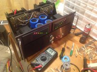
Today, I received the silicon transistor pads so I could put the amp back together.
I carefully cleaned all the power transistor sockets with deoxit; I thought maybe one of those had a crappy connection. I'm not crazy about the transistor sockets -- I don't trust they're making the most secure connection. However, they are stock (and convenient) so I just cleaned them.
I fired it back up with the 300w bulb limiter, and everything seemed better but still not right, at first. I could get the bias reading down to 140mv across an emitter resistor on the bad channel, but below that, things started to go crazy again (the light bulb got brighter and the amp shut itself off and on). However, the idling voltage was smoothly adjustable (just too high).
The other channel was fine.
Since I was out of ideas at the moment, I put *back* some seemingly changed components (according to the service manual schematics) because others have suggested these were changes in the production run of the amp. I thought maybe they were done by a tech, but maybe not.
The two changes were (maybe you can explain these to me, because I don't know why they may have been made):
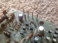
Instead of R4 being 22K (according to the service manual schematic I attached in the first post), there was some type of diode and an 8K resistor in series placed in this spot (see attached picture).
Instead of R32 being 680 ohm, it was 470ohm.
Both channels had these changes when I got the amp, and when I recapped/replaced the diodes, I replaced the parts with what was specified in the service manual.
So, seeing how the changes may have been done by Harman Kardon, I put the 'odd' components back in. This seems to have fixed things (don't know why...but I'm crossing my fingers)....atleast for now -- I don't trust it yet.
However, I can get both channels to around 0V offset with no problem, and I can get both channels to idle at 50mv across the emitter resistors. Distortion in the bad channel seems to be gone.
I didn't change the components in the 'good' channel back to the original values (R4 and R32 and it seems to be stable), but I will if all stays well.
I really hope this is fixed... What do you think of this outcome?
Today, I received the silicon transistor pads so I could put the amp back together.
I carefully cleaned all the power transistor sockets with deoxit; I thought maybe one of those had a crappy connection. I'm not crazy about the transistor sockets -- I don't trust they're making the most secure connection. However, they are stock (and convenient) so I just cleaned them.
I fired it back up with the 300w bulb limiter, and everything seemed better but still not right, at first. I could get the bias reading down to 140mv across an emitter resistor on the bad channel, but below that, things started to go crazy again (the light bulb got brighter and the amp shut itself off and on). However, the idling voltage was smoothly adjustable (just too high).
The other channel was fine.
Since I was out of ideas at the moment, I put *back* some seemingly changed components (according to the service manual schematics) because others have suggested these were changes in the production run of the amp. I thought maybe they were done by a tech, but maybe not.
The two changes were (maybe you can explain these to me, because I don't know why they may have been made):
Instead of R4 being 22K (according to the service manual schematic I attached in the first post), there was some type of diode and an 8K resistor in series placed in this spot (see attached picture).
Instead of R32 being 680 ohm, it was 470ohm.
Both channels had these changes when I got the amp, and when I recapped/replaced the diodes, I replaced the parts with what was specified in the service manual.
So, seeing how the changes may have been done by Harman Kardon, I put the 'odd' components back in. This seems to have fixed things (don't know why...but I'm crossing my fingers)....atleast for now -- I don't trust it yet.
However, I can get both channels to around 0V offset with no problem, and I can get both channels to idle at 50mv across the emitter resistors. Distortion in the bad channel seems to be gone.
I didn't change the components in the 'good' channel back to the original values (R4 and R32 and it seems to be stable), but I will if all stays well.
I really hope this is fixed... What do you think of this outcome?
Well its a good outcome if its fixed 🙂
R4... what this does is supply a constant bias current to Q8 which is configured as a classic current sink. Lowering R4 allows more base bias current. That in itself has no impact on the operation of Q8 unless Q8 gain is on the low side and the bias current from 22k is insufficient. The diode (ordinary diode or zener ?) may be to improve switch off behaviour when the amp is powered down.
R32 alter the range of the bias current preset. Lowering it means the transistor is able to be turned off even more at the "maximum bias" end of the pots travel.
If it all sets up OK then that's promising. Any lack of current in Q8 would alter the whole state of the amp and could cause all kinds of issues so R4 is critical in that sense. Once sufficient base current flows then lowering R4 any further has no effect... if that makes sense. And if you had a really high gain transistor then R4 could be much higher and it would all work correctly.
Thanks for all your help and sharing your knowledge with me!! I really appreciate it.
I'll keep my fingers crossed that all is okay now. I may find someone who has a scope and can verify that everything is up to spec.
If I have any more issues, I know where to go!
Thanks again. 🙂
I'll keep my fingers crossed that all is okay now. I may find someone who has a scope and can verify that everything is up to spec.
If I have any more issues, I know where to go!
Thanks again. 🙂
Your welcome, and well done. Its quite a complex amp to work on 🙂
If it all sets up OK then that is a good sign all is well.
If it all sets up OK then that is a good sign all is well.
Well, all is still good. Amp is stable at around 1 or 2 mv of offset and the bias is fairly stable at 50mv.
Sounds excellent in my system!! Runs quite warm...
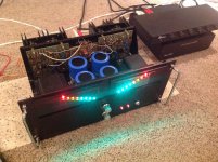
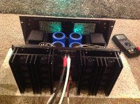
I put bright LEDS in the meters .... this was a terrible idea. (see pics) LOL I need to change them back to normal ones or be blinded.
Thanks again for your help!
Sounds excellent in my system!! Runs quite warm...
I put bright LEDS in the meters .... this was a terrible idea. (see pics) LOL I need to change them back to normal ones or be blinded.
Thanks again for your help!
Attachments
- Home
- Amplifiers
- Solid State
- Rebuilding Harman Kardon Citation 16A! Please help!!