Hi All
Got this for a few quid but needs a recap but on the filter board pics attached the two capacitors polypropylene ones I think there caps look like the ics beneath them have melted ontop and caps attached to them.
So not sure if ics have melted or the caps have been attached to the tops of the ics with looks like tar.
If there meant to be like that is there a reason as normally the tops of ics are enclosed so can't see it being a type of circuit connection.
Any help most welcome.
If on wrong thread can it be moved over please.
Attachments
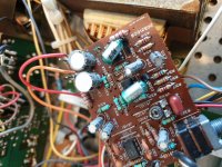
Probably the plastic sealing in the polystyrene capacitor has slightly melted when pressed against the chip but 90scaraudio is probably right as the legs of those small value polystyrene capacitors are easily broken.
I would not dump those polystyrene capacitors they last for many -many decades even 50 years or more and the "sound " better than some of the plastic alternatives.
I would not dump those polystyrene capacitors they last for many -many decades even 50 years or more and the "sound " better than some of the plastic alternatives.
Yeah what I thought but what on earth for never seen that before. There's no sign of any type of connection as pins all soldered to pcb. Could understand if it's to do with vibration or chance of it falling off very much doubt that. Mystery. Got schematic for the 40 but completely different this was obviously the top spec model.
Looks like hot melt glue, the white stuff.
The black stuff is soft, like coal tar.
And the whole scheme seems to be to absorb vibration and possibly heat, though it is a bit odd to use the ICs as a support.
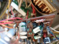
Note that the PCB holes are larger than the leads, the difference is much more than in current equipment, so all the vibration goes through the solder to the rest of the assembly.
I have not checked these, I can't, but earlier I used 0.8 mm drills for components with 0.6 mm leads. This seems like 0.6 mm leads in 0.9 mm holes.
This then seems to be from 1970 to 1985 period?
Phenolic boards with thick layers of copper, built to last?
Have fun, part of the golden age of hi fi.
The black stuff is soft, like coal tar.
And the whole scheme seems to be to absorb vibration and possibly heat, though it is a bit odd to use the ICs as a support.
Note that the PCB holes are larger than the leads, the difference is much more than in current equipment, so all the vibration goes through the solder to the rest of the assembly.
I have not checked these, I can't, but earlier I used 0.8 mm drills for components with 0.6 mm leads. This seems like 0.6 mm leads in 0.9 mm holes.
This then seems to be from 1970 to 1985 period?
Phenolic boards with thick layers of copper, built to last?
Have fun, part of the golden age of hi fi.
Last edited:
Nice one thanks for that. It seems well built and I did not know that about the solder joints. Yes there's quite a bit of point to point wiring.
Thats okay then I'll just leave those as they are its only a filter circuit with a pot. But yes bit odd attaching both to the ICs. Caps in there odd ones 90% are all electrolytic ranging from 1uf 2uf 2.2uf 4.7uf etc etc and voltages 10v upto max of 50v. Mind you the solid core wiring is starting to get brittle. Yeah think this is late 70s/1980. Some came out after this in 1988 but less power and fewer controls. So think this was a flagship model as they say. Even has a memory dial on the gain pot.
Considering the make the components pretty good was surprised. Be interesting once re capped how it sounds.
Oh and since the components are held in place by the solder and you do not know how it was handled and stored, a reflow of all the joints is to be thought of, just as insurance.
The old lead solder is less brittle than the new lead free ones, but Sansui for one were prone to dry joints.
Add to that corrosion caused by age and flux residues, that is asking for frequent maintenance.
So please take a close look with a bright light and a magnifying glass.
The old lead solder is less brittle than the new lead free ones, but Sansui for one were prone to dry joints.
Add to that corrosion caused by age and flux residues, that is asking for frequent maintenance.
So please take a close look with a bright light and a magnifying glass.
Think of it mechanically, not thermally or electronically.But yes bit odd attaching both to the ICs.
* Big fat capacitors (largest there except filtering electrolytics) with long skinny legs which can easily be cracked by vibration.
* very probably added *after* the PCB was designed, so no space available for them, close to PCB with short legs like ALL other parts.
An accident waiting to happen.
So you add them with long legs, notice they had to sheath them in black plastic to avoid shorting other parts and those "elephants in the bazaar" had to be somewhat mechanically fixed.
A drop of glue to *anything* nearby is better than nothing.
Yep will do. I never use lead free solder although it's getting harder to get hold of. But got a good stash.
Funny really because the flux is actually more toxic than the lead. Smells nice though. Thanks for advice.
Funny really because the flux is actually more toxic than the lead. Smells nice though. Thanks for advice.
Actually, they could have kept the capacitors on short legs, and put thick sleeves, pieces of pipe really, and bonded those to the PCB.
That would mean needing some space on the PCB.
Maybe they changed the capacitor spec from something else to these, and by that time the PCB were ready.
Whatever, I do not think many of those old sets are in working condition any more.
By softer I meant the softest available leaded solder, 60/40 is softer than 67/33 I think.Now you are restricted to what you can get, of course, but try to use the softest in hand.
Funny enough thats what I have 60/40 plus it melts and flows beautifully and always leaves a shinny joint plus the iron does not have to be incrediblyhot. This lead free is nightmare to get off and at times looks like a dry joint on drying plus you need the iron so hot. So always worry your gonna damage components. You can still get in the States but postage cost to UK is ridiculous.
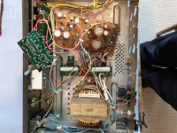
Finished main board yesterday so just the other boards now. I wanna regrease the outputs plus there seems to be two sensors one on rectifier board and the other is glued to the transformer something else never seen before. But to get the board off the wiring is all attached via vero pins either wire wound on but now brittle so thats gonna snap for sure or its heavily soldered to them. So thinking on that one.
One thing for reference the smaller caps are all marked say 1/50 or 4.7/25 etc worked that out threw me initially so its 4.7uf 25v so maybe of some help in future.
I think there could be a little more to the bonding of the caps to the IC. Sometimes there are even issues with microphony in some builds, others not, depending on the design and component sources. Even so, I'm surprised that Tandy Corp. (Realistic brand), would have been so careful to minimise noise. Perhaps it was just a precaution, afterthought or just a convenient way to hold the capacitors during rework.
Anyway, here are some useful facts about the important qualities of most capacitor types found in audio systems: Capacitor Characteristics. Work your way through the rest of the site too. Its also the current host site of Geoff Woods' "The class A Amplifier Site (TCAAS)" and a goldmine of pro. advice to beginners, DIY repairers and audioholics alike.
Anyway, here are some useful facts about the important qualities of most capacitor types found in audio systems: Capacitor Characteristics. Work your way through the rest of the site too. Its also the current host site of Geoff Woods' "The class A Amplifier Site (TCAAS)" and a goldmine of pro. advice to beginners, DIY repairers and audioholics alike.
Cheers Ian I’ll have a look through that.
Yes Definitely a reason why they are attached to the ICs. As said that’s the filter circuit but it’s also interesting that they even gone to the effort of sleeving the legs. But the polys I’ve not come across that colour on the outer bands before usually red. But although the wiring is a mess which is no different to valve gear really. But there’s some good components in there just a shame no schematic as there are also quite a lot of trimmers in there. Even those Honda 10watt power resistors are very good quality they will never fail.
But yes there’s a lot of buff re sound of capacitors but I think it’s more to do with where there placed in the circuit plus you want the right spec in there otherwise your gonna create an unbalanced circuit thinking from a physics point of view. But the reason the unit may sound different is because you’ve put new caps in so it’s gonna sound well should do like it did when new. As nothing has drifted you’ve cut leakage down etc. No different from an old 200 000 mile engine and replacing a brand new one in there it’s gonna run like it did when new. So less fuel consumption lower emissions better throttle response etc. So that’s how I perceive capacitors. But definitely have a good read.
Cheers
They could be sensors for transformer temperature, maybe to protect it.
Without a schematic it is hard to tell.
How did you find the joints during reflow?
Any doubtful ones?
Here solder was about 15 quid a kilo, maybe it is 20 now, copper has gone to 10 quid, it was 6 quid in 2019.
Without a schematic it is hard to tell.
How did you find the joints during reflow?
Any doubtful ones?
Here solder was about 15 quid a kilo, maybe it is 20 now, copper has gone to 10 quid, it was 6 quid in 2019.
Yeah I think that's what they are if I get the rectifier board of I'll take some pics and post.
No none to be honest all fine so far still working on it had to buy more caps missed around ten of them unfortunately my cat got habit of distracting me so was be peed off there. So there coming tomorrow. Kilo of lead price wise not sure not bothered to check it to be honest.
Reflow fine for me as you don't need the iron too hot I tend to tin the tip flick off excess wipe on wet sponge then quickly re tin tip place solder over joint quickly touch with tip of iron job done. Nice shinny joint. Thats my method. Nothing then overheats. I use a sucker for removing then clean off with wick. But as I mentioned this lead free solder well I've found it much harder to remove unless the iron is hot. Plus obviously I have to tin the tip with lead free solder not lead solder. Bit of a pain really. The damage is usually what I've found in past is too much heat can end up lifting the track off unless it's already damaged so it will lift off anyway. Is that what you meant or did I go on a bit there ha.
Lead free is antimony bismuth alloy with a little silver at times, it needs 260 Centigrade to melt.
Regular lead tin solder melts about 230 or less, so the trick to reflow lead free joints is to actually add leaded solder, and let it blend in the melt.
To avoid tracks getting damaged, heat the joint no more than 5 seconds at a time. You can repeat later after a few minutes if you feel it was not done properly.
I use this method when parts need replacing, add lower temperature solder, then remove with sucker or wick.
Also, lead free tends to be brittle, and can fail with dry joints so it is better to add regular solder like above throughout the board whenever you open up a piece of equipment, at least the ones you can...SMD and others may not be within your comfort zone.
Last edited:
- Home
- Amplifiers
- Solid State
- Realistic mpa90 power amp are components melted