I have no idea how permeability can change with level and freq.
Weird stuff, transformers!
Jan
Weird stuff, transformers!
Jan

Yes you do, you know the BH curve is S-shaped, therefore its slope (permeability) changes with level. Changes with frequency are a bit weird though!I have no idea how permeability can change with level and freq.
That's right. Take a look at some hysteresis curves. In an EI transformer, the effect is tamed by the air gap that adds a magnetic resistance that tends to mask the effect, but a toroid is essentially ungapped, so the variation is much larger. Further, toroids don't like the slightest sniff of net magnetising current - it causes their inductance to fall catastrophically.
From a textbook:
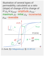
Magnetic permeability, μ (also written as mu) - a property of a given material or medium, quantifying its magnetic response of flux density B when subjected to magnetic field strength H.1)2) Magnetic permeability is proportional to the ratio of B and H changes: μ = ΔB/ΔH. Several different kinds of permeability can be defined, depending on the character of changes in B and H.
mu=dB/dH is the slope of the green curve in the following picture.
Small near demagnetized: initial mu.
Rising with magnetic field strength H.
Until max mu.
Falling again towards saturation.
Attachments
Obviously missing an airgap (and measured at the peak of the cores permeability)I'm currently experimenting with a VDV-GIT80 which sports 900H (measured at 50Hz) over both PP primaries.
What am I missing??
Jan
But you sure know all that 🙂
I guess my assumptioni was a bit wrong 😉In my DS it says 900H.
But what I don't understand is why the inductance varies with the measurement voltage.
I would think that inductance depends on the number of turns and the core parameters.
Do the core parameters vary with signal level and frequency?
As long as you stay within the reasonable linear part of the B/H curve, which you would, no?
Jan
What "linear" part of the BH curve you thinck you could use with the hugly varying levels in amplitude and frequencies of the audiosignal ?
Offcourse a magnetic core, and therefore the inductance, is extremly voltage and frequency dependend, especially if ungapped..
You must put an airgap in serial with the magnetic path to linearize.
But even in SE, with an airgap and dc-premagnetisation, you have to accept at least some 25-30% of signal dependend inductance variation if you want to have any reasonably inductance remaining.
Last edited:
It is true, with the provision that there is also some effective capacitance associated with the coil. If that is resonant with the inductance in the audio band, then the effective inductance will indeed vary with frequency, whether it is air core or iron core.
Also, you should remember that the primary's impedance is really a reflected impedance. For example, if you have a transformer specified at 4K ohms primary and 8 ohms secondary, that means the impedance seen by the primary if you are driving an 8 ohm load. Then, if you replace the 8-ohm load with a 16-ohm load, the reflected impedance to the primary is now 8K ohms, i.e., it is a ratio.
There is also something somewhat comparable to a skin (lamination thickness) and proximty (stacking hight) effect in cores.
The "effective" crossectional area of a laminated core is frequency depend do to eddy currents.
The rhinner the lamination and the higher the Si content the smaller the impact.
The "effective" crossectional area of a laminated core is frequency depend do to eddy currents.
The rhinner the lamination and the higher the Si content the smaller the impact.
Fortunately inductance is just a parasitic load on the output valves, in parallel with other loads. So its effects can be minimized by reducing source impedance, a component of the total parallel impedance appearing at the primary. If otherwise, nothing would have ever worked.
All good fortune,
Chris
All good fortune,
Chris
That's a nice picture. I know that curve of course, but had always assumed that an audio xformer would operate in the linear part of it.From a textbook:
Magnetic permeability, μ (also written as mu) - a property of a given material or medium, quantifying its magnetic response of flux density B when subjected to magnetic field strength H.1)2) Magnetic permeability is proportional to the ratio of B and H changes: μ = ΔB/ΔH. Several different kinds of permeability can be defined, depending on the character of changes in B and H.
mu=dB/dH is the slope of the green curve in the following picture.
Small near demagnetized: initial mu.
Rising with magnetic field strength H.
Until max mu.
Falling again towards saturation.
With changes in permeability of a factor 10 depending on level and frequency, that must be seriously nonlinear.
Why do people still build amplifiers with output transformers?? For sentimental reasons?
Jan
The much maligned Single Ended Triode amplifiers do operate on the (reasonably, kinda-sorta) flat part of the curve, which gives them another kind of monotonicity beyond their inherently class A valve operation. Wasteful yes, but so is learning to play a piano. Different strokes for different folks.
All good fortune,
Chris
All good fortune,
Chris
The best you can do is wind up 100 turns and put in the lamination as tightly as you can, and measure the inductance. From this you can calculate mu or the number of turns for a desired primary L.Does anyone know a way I can determine an Inductance formula for this lamination ? Thickness of 0.5mm. Are there any safe approximate equations I can use without any manufacturers details?
I think your 0.5 mm lamination is for mains transformers, not really suitable fof OT. Also the color and crystal structure can reveal it visually. You need a 0.35 or 0.3 (0.25?) mm lamination with light grey homogenous surface, not the darker "dynamo steel" with visible crystal domains. Anyway, you can try...
Booth formulas are not correct.Hey guys ! I have been building an output transformer to the Manual written by Robert G Wolpert.
A measure for primary inductance depending on cutoff frequency , -1db loss at the lower bound frequency f1 is given by:
L = (Primary Impedance)/(pi*f1)
here using my primary value of 4KOhm and frequency of 20Hz , I get an inductance value of ... 64 Henry. Which seems like a lot and not a very realistic value to design towards.
However , another equation that works using maximum flux density (B) is ;
N = (V * 10^8)/(K * A * f1 * B * 6.45) where A is the Bobbin Area and K is the stacking factor.
here using my values of V=346 , A=3.68 , f1=20 , B=14KGauss , a much more reasonable value of 1302 turns is shown.
So my question is , do I go ahead with the 1302 Primary turns to hopefully wind up a whopping 64 Henry primary inductance ? Or should I be less ambitious and go for -3db loss at 20Hz , or even -1db loss at 40Hz or so ?
Thank you for the help guys !
Firest one not considering the internal resistance of the tube just the transformer? Llike the transformetr is "working" out of the tube system? Alone?
So for the first aproximate formula @ -3db :
Lp = [1 / ( 2 x Pi x F)] / [(Ri x Ra) / (Ri + Ra)], Ri=internal resitance of the tube in working point, Ra=transformer anode load value
.
Other formula You gave for inductance in function of turns dont consider the core material with specific permeability and magnetic gap.
So with the same number of turns and same gap, same core dimension, same wire dia. we can have dramtic diference in inductance?
.
cheers
You are right: the sentimental factor is very strong, especially nowadays. But the nonlinearity can reduce by relatively low driver impedance and the "state of the art" core materials. The core magnetizing causes additional current component, parallel the main current. If the core permeability is enough great, the additional current component will small. The small component's nonlinearity can't generate big distortion. Better situation is the huge permeability AND linear B-H curve (for example nanocrystalline material). Similar situation can see at the low generator impedance: the distortion's EMF will shunted by driver. In the end, the distortion will be smaller than one would expect from the B-H curves at first glance.That's a nice picture. I know that curve of course, but had always assumed that an audio xformer would operate in the linear part of it.
With changes in permeability of a factor 10 depending on level and frequency, that must be seriously nonlinear.
Why do people still build amplifiers with output transformers?? For sentimental reasons?
Yes ! Going to test it soon , need to purchase a LC meter though. Hopefully those cheap high range ones on Aliexpress will do. I think its some sort of Silicon Steel lamination ; it has a very stainless steel look to it and is a nice light metallic grey. Unfortunate I picked out the wrong thickness , will have to work with this though , the prices for brand new unused laminations is insane over here.The best you can do is wind up 100 turns and put in the lamination as tightly as you can, and measure the inductance. From this you can calculate mu or the number of turns for a desired primary L.
I think your 0.5 mm lamination is for mains transformers, not really suitable fof OT. Also the color and crystal structure can reveal it visually. You need a 0.35 or 0.3 (0.25?) mm lamination with light grey homogenous surface, not the darker "dynamo steel" with visible crystal domains. Anyway, you can try...
When you measure inductance with a cheap LC meter have in mind what has been said before.
Inductance of iron core coils drop with rising frequency and also drop with low excitation.
My cheap meter e.g. tests at 500 Hz and no more than one or two Volt amplitude.
The value you get with such a meter can be much lower than what you actually have at - say - 50 Hz and 100 V amplitude.
A simple alternative methode to get more relevant numbers could be to apply a 50 or 60 Hz AC voltage of your choice from a mains transformer and simply measure Voltage V and Current I with your multimeter.
Inductance can then be calculated from L = V / ( I * 2 * pi * F )
... ignoring DCR which should be much lower than inductive impedance anyhow ...
Last edited:
In the last few years I've rewound 6 guitar amp transformers - all bar one used 0.5mm laminations - while it is nice to have M6 0.36mm laminations you can wind a decent sounding output transformer using ordinary power transformer laminations.
Late last year I compared different output transformer iron using the same winding, the test amp was a quickly knocked up single channel amp - I wound a copy of the Dynaco Z565 output transformer - stacked it with 'ordinary' 0.5mm power transformer iron and then ran some frequency response square wave and distortion tests. I ran the same tests after restacking it with M6 GOSS 0.35mm laminations - while I couldn't carry out any A/B listening tests, as I only had the one mono amp both sounded perfectly fine - there was a minor difference but it certainly wasn't night and day, most of the difference was in the bottom end performance below around 50Hz, increasing the stack size of the ordinary laminations, would certainly improve it's low end performance.
Late last year I compared different output transformer iron using the same winding, the test amp was a quickly knocked up single channel amp - I wound a copy of the Dynaco Z565 output transformer - stacked it with 'ordinary' 0.5mm power transformer iron and then ran some frequency response square wave and distortion tests. I ran the same tests after restacking it with M6 GOSS 0.35mm laminations - while I couldn't carry out any A/B listening tests, as I only had the one mono amp both sounded perfectly fine - there was a minor difference but it certainly wasn't night and day, most of the difference was in the bottom end performance below around 50Hz, increasing the stack size of the ordinary laminations, would certainly improve it's low end performance.
- Home
- Amplifiers
- Tubes / Valves
- Realistic inductance value in Output Transformer