What is it about these pipes that makes them resonate at different frequencies if they are still the same length from end to end?
Difference in mass.
But why bother you already know the answer.
That's how a discussion works.
I raised points, you didn't agree with them and then you left. If none of the points I made have any validity doesn't matter - I was thinking about things and I was hoping that a few others were too. That's all.
Not looking to break new ground here or discredit anyone, just to have a lively discussion and think about things in a different way.
Not all of the answers are on Wikipedia or other websites (so nicely pointed out by GM).
Last edited:
For TL speakers there is probably no other design concept with more variations the the TL. In the end for me it was lots of fun exploring but functionally the worst of the subs. Yes in specific cases in specific rooms it could be okay but for my 2¢ worth the woofer that measured flattest in the room has always been the low Q, less than 0.5, sealed box design in a really solid box.
So if the goal is to have fun the TL is the clear winner. If the goal is to make low distortion bass then the low Q sealed box is the winner.
Assuming you mean 'For speakers there is probably no other design concept with more variations the the TL', the compression horn has more design flexibility.
Fortunately for me, I found reverse tapered TLs to be exceptionally high SQ (low distortion) alignments, though similar to you, low Qtc sealed or low Fb EBS alignments proved the best overall referenced to reactance annulled compression horns.
GM
The student has to want to learn, and make the effort to understand what is being taught.
+1. So far, I've yet to see a question that can't be answered satisfactorily for getting a good basic understanding of acoustics if they can 'wrap their mind' around the fundamentals of how a sound wave is created, propagated.
GM
My life has been learning by doing, and not much reading really
And Im happy with the small bits I learn every day
Not much, but enough to keep me busy 🙂
And Im happy with the small bits I learn every day
Not much, but enough to keep me busy 🙂
Guys, We need a new name for this thread, agreed?
'Sound propagation in an acoustically small space' seems as good as any to me.
GM
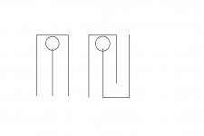
Tinitus posted a picture which doesn't get quoted (post #177) of a folded pipe with the driver at the corner, yet someone answered it would be a halfwave pipe.Ahh, a "quaterwave", open at both ends 😀What happens if we place a woofer in the middle of an open ended tube ?
I'm wondering which is true, as you can divide a reflex port into two parts. Can't you make a 1/4 wave design with multiple tubes?
Ehh, not post 177, but here it is again, if it helps you 🙂
Answer I dont have
Fore the fun of it I also attached the idea with a tapped horn using passive slave 😀
Whatever that would be good fore...low tuning, and no ripple ?
Answer I dont have
Fore the fun of it I also attached the idea with a tapped horn using passive slave 😀
Whatever that would be good fore...low tuning, and no ripple ?
Attachments
I'm not sure what your goal is. You can reduce the back wave, but the effectiveness is frequency dependent, of course, and you can easily overdamp. I've experimented with damping closer to the driver, but it can have negative results. My interest is more in pure midranges for that case. Woofers have to be allowed to breathe, so-to-speak.Concern for the back wave: Can they be reduced?
I'm interested in testing similar "obstructions", but I doubt that there's much that has not been tried by others previously. I just have not seen much in the way of objective measured results.Will it be beneficial to construct (holey) baffles or other angled partitions to obstruct or decrease the chances for back waves to get to and out of the diaphragm?
Again, I'm not sure I can answer this appropriately, I only know my own experience. I don't see it as a pressure event, as in box pressurization, that to me would be in the range below box modes (longer wavelengths). I've used strategically placed damping in PR and ported systems. That part still seems to be a bit more art than science in that trial-and-error seems to be the only way to approach it. I'd like to find a better way to reduce the standing waves without over-damping. The only real problem is the internal box modes, the rest are damped easily of course.Are the back waves a pressure event? If so, does it follow that obstruction is of little relative value?...I believe this is frequency related.
This is an area I'd like to investigate a bit more, just to satisfy my own curiosity.I now will focus on the "line of sight" to the back of the diaphragm. I'll let the magnet and supporting structure do some of the dirty work for me.
Dave
Dave,
...as my thoughts move along...
I don't want to over damp...I want to allow the backside of the diaphragm to breathe.
I'm considering something that could be called a labyrinth. This would provide a clear path for the back wave going away from the driver. The surfaces would be angled to accomplish this. This would (I think/I intend) allow the back wave unimpeded entry into the enclosure. At the same time the surfaces would make a longer path length necessary for wave energy to return to the back of the diaphragm.
I agree measurement is necessary. My choices are more "seat of the pants" at the moment. This has me favoring Bob Brines' method of CLD under 1" Owens Corning 703.
Thanks for all
...as my thoughts move along...
I don't want to over damp...I want to allow the backside of the diaphragm to breathe.
I'm considering something that could be called a labyrinth. This would provide a clear path for the back wave going away from the driver. The surfaces would be angled to accomplish this. This would (I think/I intend) allow the back wave unimpeded entry into the enclosure. At the same time the surfaces would make a longer path length necessary for wave energy to return to the back of the diaphragm.
I've been able to bring the box modes into cancellation (sim's, +/- 1.5 dB) through careful dimensioning of the case...though I don't believe this means those frequencies no longer return to the back of the diaphragm.I'd like to find a better way to reduce the standing waves without over-damping. The only real problem is the internal box modes, the rest are damped easily of course.
I agree measurement is necessary. My choices are more "seat of the pants" at the moment. This has me favoring Bob Brines' method of CLD under 1" Owens Corning 703.
Thanks for all
Last edited:
In short... YES. But does it matter?
A thought experiment for you:
In a simple fold, the area of the line changes as you pass around the bend - it expands, then contracts, then expands again, then finally contracts to the area of the line after the bend. You can measure the effect this fold has on various frequency waves. You'll find, as have many others, that low frequencies - long wavelength relative to the pipe length) pass around the fold with very little loss or reflection. High frequencies - short wavelengths - reflect strongly from the fold.
Now imagine straightening the bend back to a straight line, but keep the area changes - in other words, an expansion-contraction-expansion-contraction of the line. Now measure the effects on the various frequencies again. Surprise, surprise, surprise...
"Aha", you say, "I could add curved "fillets" to my folds to ensure they have a constant area around the bend." Well, yes, you could, if you need your line to function well at higher frequencies. It's just that for most applications of transmission lines and tapped horns etc, efficient transmission of higher frequencies is undesirable. They are to be suppressed, not transmitted.
So getting back to your original point, the resonances of the two pipe sections are (hopefully) above the designed operating range of the system. There is some logic in having more folds in a line rather than fewer, since the resulting higher order resonances are at higher frequencies which (a) will hopefully not be present in the first place due to the speaker crossover, and (b) are more easily damped by lining or stuffing, which becomes more effective as the frequency increases.
Don. Everything you state is true, and its also already within my realm of knowledge.
and it DOES matter. if a sections form say half a third or quarter of the total length then given a fundamental tuning frquency of 40 Hz the sectional resonsances ARE indeed signinficant. i mean 40 & 80hz, or 40, 80, & 120Hz , or lastly 40, 80, 120, 160Hz; respectively. some of these resonances may coincide with the harmonic nature of an unstuffed tube, and nullify them, if cleverly designed, which COULD be an advantage. in fact it would be a good way of designing a TL. however to ignore the resonances is as good as saying they dont exist, something which mathematicians do at will, subject to their opinion on the factor's importance. whilst this simplifies the math, and if done well doesnt reduce accuracy alot, in some cases it changes rather too much. In a TL. it would be like me designing a tube length and area, ignoring the common 'no-no's' and square-rooting the area to define the closed end area. in such a way i would have width and depth the same size. good for a stronger pipe behavior, but bad for reducing colouration by the already present pipe resonances.
in fact ANY spurious resonance is important. excluding them is like modelling a BR for flat resp and ignoring the other resonances and expecting it to behave entirely like the math. It doesnt, as the math is correct but for only the conditions and data range it is designed for.
point being:
a straight pipe behaves like the theoretical model most closely. The further we stray from that model the less applicable standard pipe theory and math actually is. the more variables that are introduced, the higher potential error, and the more complex the math becomes. hence a folded pipe, IMHO, really needs a seperate calculation to that of a assumed non folded one, since it is not straight. the differences may be small, but sometimes the end user would like to decide that for themselves, and not have a mathematician decide that they know whats best for them, and do it for all.
Last edited:
What's up?
Catching up a bit for any folks that may be interested in my 'Peanut Gallery' responses, Saturday was way too nice to spend it indoors.
GM
Tinitus posted a picture which doesn't get quoted (post #177) of a folded pipe with the driver at the corner, yet someone answered it would be a halfwave pipe.
I'm wondering which is true, as you can divide a reflex port into two parts. Can't you make a 1/4 wave design with multiple tubes?
Both. Each 'stub' is a 1/4 WL resonator, ergo their combined responses sums to a 1/2 WL resonator.
FWIW, here's a write-up I did to hopefully help folks understand, design such a speaker, though to date I'm not aware of anyone trying it: http://www.diyaudio.com/forums/subwoofers/79102-tom-danleys-tower-power-3.html#post1046340
Note too that since I wrote this it can now be simmed in Hornresp.
GM
Fore the fun of it I also attached the idea with a tapped horn using passive slave 😀
Whatever that would be good fore...low tuning, and no ripple ?
Well, it would roll off its HF response somewhat, but probably not practical except possibly on a small, high Fp TH since a large, low tuned TH will have such a large vent area and acoustic end correction that the number of large, long excursion PRs required would make it a very expensive way to roll off/damp its unwanted HF output.
GM
FYI all, the OP has now pitched camp over at audiokarma.org speaker forum
Fact from Friction - AudioKarma.org Home Audio Stereo Discussion Forums
He's like an evangelist - spreading his gospel all over in the hope some will become believers.
Fact from Friction - AudioKarma.org Home Audio Stereo Discussion Forums
He's like an evangelist - spreading his gospel all over in the hope some will become believers.
FYI all, the OP has now pitched camp over at audiokarma.org speaker forum
Fact from Friction - AudioKarma.org Home Audio Stereo Discussion Forums
He's like an evangelist - spreading his gospel all over in the hope some will become believers.
They're already handing out the popcorn
I know its not the brightest question, and basic stuff, but is there an easy way to explain the difference of 1/2wave and 1/4wave, and the end result of one or the other ?
Don. Everything you state is true, and its also already within my realm of knowledge.
and it DOES matter. if a sections form say half a third or quarter of the total length then given a fundamental tuning frquency of 40 Hz the sectional resonsances ARE indeed signinficant. i mean 40 & 80hz, or 40, 80, & 120Hz , or lastly 40, 80, 120, 160Hz; respectively. some of these resonances may coincide with the harmonic nature of an unstuffed tube, and nullify them, if cleverly designed, which COULD be an advantage. in fact it would be a good way of designing a TL.
I don't see how this could be made to work. The resonances of the line sections are a mixture of close/closed, closed/open, and open/open resonant paths. In short, a mess. But I'll make an attempt to model it in Akabak and see what happens.
point being:
a straight pipe behaves like the theoretical model most closely. The further we stray from that model the less applicable standard pipe theory and math actually is. the more variables that are introduced, the higher potential error, and the more complex the math becomes. hence a folded pipe, IMHO, really needs a seperate calculation to that of a assumed non folded one, since it is not straight. the differences may be small, but sometimes the end user would like to decide that for themselves, and not have a mathematician decide that they know whats best for them, and do it for all.
Fair enough. But my own point was not that fold resonances don't matter or can be ignored, but that in quarter-wave type applications (TL, tapped horn etc) they are usually undesirable and should be suppressed. This is distinct from most true horns, where fold resonances should be avoided.
I know its not the brightest question, and basic stuff, but is there an easy way to explain the difference of 1/2wave and 1/4wave, and the end result of one or the other ?
1/4 wave has one end open and one closed (ie different boundary conditions at the ends), a 1/2 wave line is either both open or both closed (ie same boundary conditions at the ends)
dave
1/4 wave has one end open and one closed (ie different boundary conditions at the ends), a 1/2 wave line is either both open or both closed (ie same boundary conditions at the ends)
dave
I always remember it this way: if you draw a single sine wave, a point half way down the wave from the start is the same as that start point (disregarding phase). A point a 1/4 wave down the curve from the start pointis at max while the start point is at zero.
Why the start point? Well, you could also take the 90 degree (max) as the start point. Thing is, if you have a standing wave in a closed pipe, the end caps are steady so there's no wave movement: zero points.
In a 1/4 wave tube, the closed end is at zero movement, the other is at max. Just like on the sine wave you just drew.
jd
- Status
- Not open for further replies.
- Home
- Loudspeakers
- Multi-Way
- Real Expert or Just Self Proclaimed