I've mentioned that the amp is unity gain, that is obviously around the loop that provides oscillation, however the bridged-T notch filter provides 15.6 dB of notch depth giving the amp 15.6 dB of gain and then the positive feedback path should have 15.6 dB of attenuation to provide proper feedback for oscillation. Away from the notch the negative path has no attenuation and the amp is then unity gain at frequencies where it might spuriously oscillate. Here is a link to Dick's discussion on the IG-18 with excellent coverage of the bridged-T filter:
IG-18 #1
I noticed that the design is very sensitive to any Cdom capacitance and this is due to the diff pair not having enough available current to charge the capacitance, it slew rate limits at higher frequencies with even 10 pF of Cdom capacitance. This means that the design will be very sensitive to the internal capacitances of the VAS transistor.
I've attached an LtSpice simulation of the stock IG-5218 (R3 = 56K and C5 = 100uF) where I removed the positive feedback loop so that we can look at the performance of the amp in the 15.6 dB gain configuration. I simplified the negative feedback loop for flat response as an amp rather than an oscillator. It shows all of the DC bias issues that I've mentioned. Note the imbalance in Q2 and Q3 Ic currents, and then how Q2 current clips when the experimental Cdom network is connected and the output shows signs of slew rate limiting.
Also note the currents in R8, R10, and R20.
Attachments
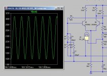
Here is the sim file showing the frequency response with the negative feedback network set up normally for 100 kHz oscillation and the positive path open and driven as an amplifier. The roughly 15.6 dB of gain is clearly seen at 100 kHz and there is some peaking in the response up around 10 MHz.
The circuit can be observed as an oscillator by changing R100 to 1000 Meg and tying in the 900 ohm resistor simulating the lamp to the feedback trim center point. Change the simulation type to transient. The oscillation builds and then clips due to the fact that the resistor does not provide amplitude control as a real lamp would.
I just noticed that if you connect the Cdom network it does not clip.
Attachments
Last edited:
Note the imbalance in Q2 and Q3 Ic currents, and then how Q2 current clips when the experimental Cdom network is connected and the output shows signs of slew rate limiting.
Also note the currents in R8, R10, and R20.
Forgot to update this after I fixed the reference designators in the simulation to match the original schematic. Here it is corrected:
Note the imbalance in Q1 and Q2 Ic currents, and then how Q1 current clips when the experimental Cdom network is connected and the output shows signs of slew rate limiting.
Also note the currents in R13, R14, and R215.
In the absence of a lamp model anywhere on the net that I could find I made one.
The lamp models the VI behavior of the SYL-90 lamp used in the Heath IG-18 models.
The model emulates the lamp converting the VI curve to resistance.
A resistors behavior is modified to follow the resistance curve of the SLY-90 as a function of the voltage across the resistor, AKA lamp.
Dick provided the VI data from his IG-18 lamp.
Unzip the file and install the .sub and .sym files in the LT spice library sub and sym file folders.
Open the .sub file in LT spice to view the sub circuit.
If anyone is interested in how this was done then I will document the procedure.
Cheers,
David.
Attachments
Last edited:
Wow! Nice work gentlemen! Thank you David and Dick.
Are either of you on the Yahoo LtSpice group and if so, do you know if anyone has done an oscillator example like this there? I'm a member but have not looked carefully at the uploaded files there.
Are either of you on the Yahoo LtSpice group and if so, do you know if anyone has done an oscillator example like this there? I'm a member but have not looked carefully at the uploaded files there.
Wow! Nice work gentlemen! Thank you David and Dick.
Are either of you on the Yahoo LtSpice group and if so, do you know if anyone has done an oscillator example like this there? I'm a member but have not looked carefully at the uploaded files there.
Thanks Pete.
I never thought of looking there.
I found another lamp model in the group files.
It's done completely differently than this one and has a much nicer lamp symbol.
Have a look.
I don't know where one could get such detailed information on a lamp to customize
a lamp for this model.
At least mine is DIY friendly. Measurements taken from the lamp.
Attachments
I've mentioned several times that this unit is very touchy. There are large disturbances in the output if I tap the circuit board and especially the lamp. Has anyone else observed this, is it normal for this unit? I've looked for cold solder joints and cracked lands in the PC board and have not found any. Is the lamp "microphonic"? Perhaps I need to replace the lamp.
I've purchased a few more lamps so that I can prototype another unit with new parts - I might just use an OP amp since that seems to be the logical way to go. It is easier than building up the amp to a Jensen 990 level for example and obviously the HP 239A has outstanding performance with an OP amp as Dick has shown:
IG-18 #3
There are some challenges in this design. The 10V RMS output really pushes many OP amps to their slew rate limits and certainly to higher distortion especially at 110 kHz and into a 600 ohm load. I believe that this can be solved by having the OP amp based oscillator put out something like 1 to 2 V RMS and then use inverting OP amp buffers to increase the output to 5 or 10 V RMS. OP amps are inexpensive so the amplification could be done in 2 inverting stages. Might make sense to put one stage in front of the attenuator and another after in order to make the output less sensitive to differences in loading.
The lamp is a limitation in low frequency distortion due to the thermal time constant and the obvious solution is to use a FET as is done in the HP 239A.
I had not planned to spend too much time on this, especially for the basic mod, so I might just abandon simplistic upgrades to what I view as a somewhat flawed design.
Last edited:
I've mentioned several times that this unit is very touchy. There are large disturbances in the output if I tap the circuit board and especially the lamp.
That's to be expected, let's say a tap to the case moves the potentiometer a tiny bit -- the frequency changes and the whole loop has to restabilize itself. A tap to the lamp changes it's impedance momentarily...
Yes, I see your point, and the gain control loop has a long time constant so that contributes to it taking a long time to settle. The feedback pot seems to have too much range and is also very sensitive. I'll look into reducing the range.
Anyone know of where I can find a copy of Bill Hewlett's Masters thesis online?
Here is his patent:
VARIABLE FREQUENCY OSCILLATION - Google Patents
It seems that the lamp requires DC bias in order to provide a stable operating point. Heath provided this through the DC offset via R5. Removing R5 in the simulation above with the lamp shows the issue. Wondering if there is a better lamp, probably better to just move to FET control as in the 239A.
I have found that various improvements often result in either HF oscillation, or squegging (motorboating) and it seems that the DC bias on the lamp helps to avoid the LF issue. I don't have a lot of experience using lamps in oscillator circuits but it seems that there are conflicting requirements. First, the lamp is required to maintain a gain of one around the loop in order to support oscillation. A short thermal time constant is required in order for it to reach thermal equilibrium in a reasonable amount of time. However, at LF it is possible for the thermal time constant to be so small that the temp varies between the peaks and zero crossings of the waveform leading to increased distortion. The resistance should very slowly adjust to maintain the gain of one as the amp gain changes due to variations in temp and Vcc over time but not (or minimally) over a single period of oscillation. This is why 4 bulbs are used for low distortion at LF as can be seen in Figure 40 of LT's AN43 and one bulb for mid and HF:
www.linear.com/docs/4134
I've not seen a detailed analysis of how the bulb should be biased for proper control in a low distortion oscillator. One reference suggested that it should just dimly glow. This makes sense since if the bulb runs hot then, with the large temperature differential to ambient, it will tend to cool much more at LF during the zero crossings.
I'd like to see a detailed analysis of the lamp biasing. It is non-linear and therefore not easy to solve.
I happen to have an HP 202C that I've not used in probably 15 years that I pulled out to take a look at. Such nice build quality! I did a google search and came across this HP Journal issue from 1956, that discusses the new balanced oscillator designs and includes some analysis showing that DC on the lamp is not a good thing - increases 2nd harmonics:
www.hpl.hp.com/hpjournal/pdfs/IssuePDFs/1956-02.pdf
Also discusses a zero output impedance tube amp stage employing positive feedback.
Found schematics for the 200C that is very similar to this unit and they use two 250V lamps in series.
www.hpl.hp.com/hpjournal/pdfs/IssuePDFs/1956-02.pdf
Also discusses a zero output impedance tube amp stage employing positive feedback.
Found schematics for the 200C that is very similar to this unit and they use two 250V lamps in series.
Last edited:
The HP 202C looked so clean that I decided to power it up and believe it or not it works. Measured 21 V RMS on the two series connected 250V bulbs. Also measured about 4% THD at 1 kHz, looks like there are some sidebands that are probably due to hum in the signal. 60 Hz is about 80 dB down. There are not a lot of caps in this design, looks like all the electrolytics are in the power supply.
This is off topic, but I wanted to see where the lamps were biased relative to their rated voltage.
This is off topic, but I wanted to see where the lamps were biased relative to their rated voltage.
There's a Tektronix SG-505 "Parts" unit available on EBAY -- shouldn't be too difficult to fix up -- I have no affiliation with the seller: Tektronix SG-505 ULTRA Low Distortion Audio Oscillator | eBay
Thanks to a little prodding from a non-working GR 1562-A SLM calibrator, I needed to think about lamp characteristics more concretely. David did a nice job on the curve plotting for the 90MB, and I was led to think about renormalizing the curves.
My little page on lamps generalizes to basically every incandescent lamp and will help (I hope) folks to understand where in it's VI curve a lamp should best be used in an oscillator -- and it is not at the point where it is glowing, dimly or not. See here:
Lamps for stabilizing oscillators
My little page on lamps generalizes to basically every incandescent lamp and will help (I hope) folks to understand where in it's VI curve a lamp should best be used in an oscillator -- and it is not at the point where it is glowing, dimly or not. See here:
Lamps for stabilizing oscillators
Thanks to a little prodding from a non-working GR 1562-A SLM calibrator, I needed to think about lamp characteristics more concretely. David did a nice job on the curve plotting for the 90MB, and I was led to think about renormalizing the curves.
My little page on lamps generalizes to basically every incandescent lamp and will help (I hope) folks to understand where in it's VI curve a lamp should best be used in an oscillator -- and it is not at the point where it is glowing, dimly or not. See here:
Lamps for stabilizing oscillators
Once again, nice work Dick,
Not sure were I read that about dimly glowing but I can see from your data that it is incorrect. I've been swamped with other work lately and I did not want to spend much time on the IG-18 anyway so not sure if I'll get back to it or not.
I'll probably build something from scratch, either the HP-239 or Bob C's state variable. Leaning toward the state variable given that it is also used in the early Audio Precision system. I'm also more interested in something with computer control for automated tests:
http://www.diyaudio.com/forums/equipment-tools/194243-audio-test-equipment-computer-control.html
Last edited:
- Status
- Not open for further replies.
- Home
- Design & Build
- Equipment & Tools
- Re-greening the Heathkit IG-18