Hi Thomas,tube-lover said:Dear all,
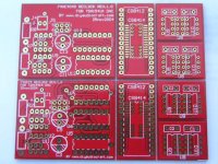
I was design two re-clock of the TDA1541a non-oversampling DAC. Test print also print out already.
Any comment for the re-clock can advise.
Pls ee the test print of the two re-clock in one PCB.
thx
thomas
A schematic of the reclock you envision would be more informative.

Re: RE-clock for the TDA1541a non-oversampling DAC./Schematic
Hello Thomas,
Did you attach a schematic to your post?
I did not see any scheme.
😕
tube-lover said:dear Elso Kwak,
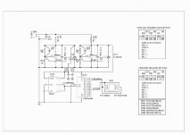
I had two re-clock fit in one PCB. This is the schematic for one. any comment for this??
thx
thomas
Hello Thomas,
Did you attach a schematic to your post?
I did not see any scheme.
😕
Why 2 paralleled 431? I assume one is enough, those logic ICs certainly don't draw more than 100mA. Paralleling such low impedance shunts could cause more problems than solutions.
And, from what I've understood from the schematic, it only reclocks the bit clock (in fact, it's not reclocking but it creates a new bit clock)
why not reclocking the 3 (or 4) lines?
And, from what I've understood from the schematic, it only reclocks the bit clock (in fact, it's not reclocking but it creates a new bit clock)
why not reclocking the 3 (or 4) lines?
BUFFER RESISTORS
You could try to place a 100ohms resistor in series of the clock path.
The minor inductance of resistos will help to reduce the overshoot.
You could try to place a 100ohms resistor in series of the clock path.
The minor inductance of resistos will help to reduce the overshoot.
This method of reclocking is stolen from DDDAC. It works I have used it my self (for one TDA1543).
The main problem is it is not synchronous to the data stream so when the oscillator drifts you will either lose a sample or use the same one twice, when that happens the resulting jitter is ...
If I read the schematic correctly the tl431 shunts are not in parallell but one is for the oscillator and another for the 4040 divider.
hifi said:This method of reclocking is stolen from DDDAC. It works I have used it my self (for one TDA1543).
Imagine where is the other "taken" from
 ... that's why Elso jumped in.
Uncle Pedja already got a headache for such things... IMO if someone wants to make some boards for a original design he should at least inform the designer and give him credits (it would be better to ask him permission).
Cheers
Andrea
hifi said:This method of reclocking is stolen from DDDAC. It works I have used it my self (for one TDA1543).
The main problem is it is not synchronous to the data stream so when the oscillator drifts you will either lose a sample or use the same one twice, when that happens the resulting jitter is ...
If I read the schematic correctly the tl431 shunts are not in parallell but one is for the oscillator and another for the 4040 divider.
IMHO it's not the best way to reclock. Assynchronous at 11MHz seems odd

And it's someone else's intellectual property!
Dear hifi & Andypairo,
this is a very common design of the re-clock. This is not stolen from any other website.
all the chips & circuits were standard one. I made this one was for my TDA1514A non-oversampling kits.
pls study.
thx
thomas
this is a very common design of the re-clock. This is not stolen from any other website.
all the chips & circuits were standard one. I made this one was for my TDA1514A non-oversampling kits.
pls study.
thx
thomas

dear Bricolo,
I had one questions.
why synchronous to the data stream will be better than Assynchronousr. Will it real be more accurancy???
not need to any matching??
pls advise!
thx
thomas
I had one questions.
why synchronous to the data stream will be better than Assynchronousr. Will it real be more accurancy???
not need to any matching??
pls advise!
thx
thomas
tube-lover said:
this is a very common design of the re-clock. This is not stolen from any other website.
all the chips & circuits were standard one. I made this one was for my TDA1514A non-oversampling kits.
pls study.
We can not study!!!!!!!!
You forgot to upload it again 🙁
tube-lover said:dear Bricolo,
I had one questions.
why synchronous to the data stream will be better than Assynchronousr. Will it real be more accurancy???
not need to any matching??
pls advise!
thx
thomas
I did not say that synchronous was worse, or that assynchronous was better.
Assynchronous works because it's own clock is at a (much) higher frequency that the signal you want to reclock. So even if the 2 clocks aren't in phase, the difference can be negliged. Have a look (just a look 😉) at Elso's ASR
Synchronous reclocking works (not necessarely) with the same frequency as the main clock. And as its name is self explicit, the 2 clocks are synchronous (you can use the same clock for the transport, dac and reclocker, or lock the reclocker's clock on the first one). You don't need a higher frequency because you want to reclock the edges of your signal, that have to be synchronous to the clock.
But imagine, like hifi said, that your reclocker's clock drifts (and it will, you will always have a phase difference between 2 free running clocks of the same frequency, and you'll also have some phase variations) you'll place an edge where your reclocker's clock thinks there should be one, but according to the main clock, there shouldn'g be one. 0 instead of 1, 1 instead of 0... This will be rare (maybe a few times per second, or a few each 10s) but adding false bits isn't the aim of the reclocker.
tube-lover said:Dear hifi & Andypairo,
this is a very common design of the re-clock. This is not stolen from any other website.
all the chips & circuits were standard one. I made this one was for my TDA1514A non-oversampling kits.
pls study.
thx
thomas
The first circuit looks identical to dddac's, which is quite "old" and well-known.
Of course it's not possible (or very hard😉 ) to use the same components for the same purpose with a different schematic
but in the first post you said "I designed" and it seemed a sort of "originality" claim, that seemed odd to me.The second instead is unknown to me... looking at the components I thought it was derived from Elso's ASR but it is not.
Will study it and maybe try it out... maybe it works even better
Cheers
Andrea
Well, you guys are funny! Whenever you see something familiar then immediately start to shout IP! Get real! You thought all of the great DIY ideas were all originated from diyaudio or someone related? diyaudio.com is the only audio DIY world? Wake up, there are hundreds thousands of active DIYers outside diyaudio.com keep creating new ideas and new things. Lots of *new* things you saw here probably had already been done by someone else long long time ago. In other words, before you open the mouth talking about IP, at least politely do some background checks first, OK? It never hurts to ask first before you come out a conclusion! Otherwise you will only make yourself a big fool and help nobody here. People will not bother to share their designs here anymore.
Reclocking WCK is not a new idea at all, definitely not invented by Doede and he has never said it's his new idea! The idea and the circuit are so simple such that everybody will come out pretty much the same implementation. So where is the IP here? If Thomas has to ask Doede's permission here, shall he also ask hundreds of people who have done the same design before?
Reclocking WCK stuff is very popular in Asia's DIY world I believe, for instance:
http://myweb.hinet.net/home1/prbstech/DAC_reclocked/Reclocked-1.htm
Look at the bottom of the page.
If Thomas intended to copy someone's *IP*, he should have had many other choices, not just Doede's.
Oh, BTW, I have seen several DAC designs in China using AD844 similar to the way Pejda did. Again, no biggie there, too.
-finney
dear Andypairo,Bricolo,etexte,hifi & all readers of my thread,
First of all I said very sorry for my BAD English & cause too much noise. My bad english & worse to choose real words to present for the re-clock cause too much missunderstanding. One more time sorry to this.
Diyaudio was a very good place to share experience from world's diyers. I understood Andypairo,Bricolo,etexte,hifi's thread, they worried the copyright of diyer's idea. Me tooooooo. So why I print the PCB in Taiwan, not in China?? I was afraid that all street
was my products. I thought all diyers develope his idea,
paid more more effort to make them idol & prefect. Me too.
I had some good friends in taiwan to help me to purchase chips in good price because they all were superior in big computor mother board factory. I also dealer of some japan product's. Parts & chips can bought in good price why not benefit to other diyers in overseas. Am I wrong???????????
I was not maintain my life in diy business, so I prepare one new item will not as big company considerate the profit first. I will considerate the best that I can use to make them prefect.
BTW, sorry to cause misunderstanding for my idea. Let us share diy experience!!!!!
this re-clock link was one of my friend told me.
pls take a look to reference.
http://pc.watch.impress.co.jp/docs/2004/1005/nishikawa.htm
this link was from japan, Japan was very serious about the copyright. So I think this circuit will not stolen from other website. So..... just for a look. OK!!
thx
thomas
- Status
- Not open for further replies.
- Home
- Source & Line
- Digital Source
- RE-clock for the TDA1541a non-oversampling DAC.