I think the term "Vapor Deposition" is a better description of the getter activation action.
Sputtering is a term reserved for electrostatic deposition of material, as oposed to vapor deposition.
I believe "Splashed" implies a liquid volume thrown against a surface.
Agreed.
In this case the material is vaporized by induction heating, and deposited on the inside surface of the glass envelope as the vapor condenses in a partial pressure (no such thing as a complete vacuum?).
Yes. It is a high vacuum, but imperfect, which is why ions exist to cause grid current.
Certainly it remains active once deposited, but to what degree a surface layer could interfere with further operation is open to discussion since totally white deposits are seen in tubes which are defective indicating they remain so.
Yes, white indicates the barium has fully oxidized and that the getter is now inert. But the question is how permeable the film remains when gas is present, because it should be so active it binds the oxygen and other gasses.
I have (or had) a 01A tube which was gassy. If I can find it, I will build an induction heater and try to see if I can recover the tube.
More data is good.
The question, however, is will a properly functioning tube with grid current from ions become a better tube if the getter material is heated.
Such a good tread, guy's.
I have some chemical knowledge from my school and university, but it has been many time ago. Reading carefully the thread, two question arise:
1) How secure is that the vapor or sublimation of the getter particles will not be itself part of the problem? ( part of the non-perfect vacuum inside the tube).
2) I have some old used UL84 tubes whose getter splash is dark gray, not silver plated mirror like. They work properly, but what make this difference? Getter mix?
Many thanks for good data provided below.
The question, however, is will a properly functioning tube with grid current from ions become a better tube if the getter material is heated.
How do you make any pure metal out of ore?
1) How secure is that the vapor or sublimation of the getter particles will not be itself part of the problem? ( part of the non-perfect vacuum inside the tube).
You identified the key problem with flashing the getter.
The vaporization of the getter must not coat other parts of the tube because this interferes with their functioning. this is why the getter is placed away from the control, emission, and target structures, and the heating is rapid so it vaporized and immediately condenses on the cooler envelope.
2) I have some old used UL84 tubes whose getter splash is dark gray, not silver plated mirror like. They work properly, but what make this difference? Getter mix?
No, different vaporization technique.
I specifically addressed that in my post No. 20: http://www.diyaudio.com/forums/tube...ate-getter-save-gassy-tube-2.html#post4875541
The short version is slow vaporization yields a heterogenous deposition of a reacted layer and then a non-reacted layer, while rapid vaporization yields a more homogenous deposition of reacted and non-reacted portions.
How do you make any pure metal out of ore?
Ahhh, but the getter is not fully oxidized. That is an incorrect assumption.
The getter deposition layer is not fully reacted, and, depending on how quickly or slowly the getter was flashed, consists of either a fully reacted layer covered by a non-reacted layer (silver, fast), or a jumble of reacted and non-reacted portions (black and silver, slow).
The getter should continue to react with any gas because it has large surface area and plenty of unreacted material. Yet we know from empirical evidence that tubes have gas because of the grid ions.
So the question is: why isn't the getter capturing them?
These ions, BTW, are usually (but not always) oxygen driven out from the metals or mica by heat, or dissociated alkali metals from the cathode coating.
I was curious if heating the getter made it more reactive and thus able to better bind those stray atoms. Because I am unsure why they continue to exist given the getter is reactive.
Ok, soo, I got the Royer oscillator working again but managed to destroy about 20 quids worth of FET's in the process.
To heat the rather large getters in a 13E1 will require around 500W of power input to the inverter. It is not very efficient but it's simplicity is a good thing as it doesn't need a phase locked loop or other means of feedback to keep it on song.
I'm leaving it for this evening as I have burned my fingers, destroyed 12 FET's and not managed to upload any photos.
I now know why I gave up on this simple induction heater. It is too simple and has way to many compromises. My tank circuit seems pretty good though.
So, I can easily heat the getters in a smaller valve even up to the size of an 25W type. I don't have any that are worn out enough to measure a difference one way or the other.
I really don't think it will be possible to measure a difference in a small signal type. It may even measure worse due to depositing getter on the mica.
This does intrigue me though and I will try again but not this evening and not for at least two weeks as I'm tied up with work.
Cheers
Matt.
I'm leaving it for this evening as I have burned my fingers, destroyed 12 FET's and not managed to upload any photos.
The start of every successful DIY project begins with a Chernobyl.
I really don't think it will be possible to measure a difference in a small signal type. It may even measure worse due to depositing getter on the mica.
This should not be an issue given that the getter is already deposited on the envelope, provided the heating is rapid and of short duration.
The vapor pressure of the barium is very low.

I'm confused on terms.
I think the getter is the "mirror flash".
It comes from a "bucket" (often ring-shaped for good RF coupling), which is pre-loaded with a thick blob of getter-stuff (thick so most of it stays good in air for assembly). After evacuation, it is RF heated, hungry metal vapor is deposited on the glass where the open side of the bucket/ring points, to form the getter.
I would think the idea of RF-heating the tube is to "squeeze out" any last dreg of getter-stuff in the bucket/ring which the factory hadn't totally vaporized.
Re-cooking the getter flash makes no sense to me. And seems likely to *emit* all the gas the getter has been absorbing, forcing a long wait for the getter to re-getter the tube.
I would think the idea of RF-heating the tube is to "squeeze out" any last dreg of getter-stuff in the bucket/ring which the factory hadn't totally vaporized.
No, that's dead, Jim.
The trough should be empty. The vapor pressure of the getter (typically alkali metals like Ba, Sr, and Ca, sometimes with a little Mg, Al, or Fe to improve the reaction) is very low. The getter trough becomes so hot everything boils off it.
The issue is whether or not the surface of the getter deposition film has a fully-reacted homogeneous layer which is preventing diffusion of gas into the interior. Because that's what is desirable in a getter. Which is why the better approach is a rapid flash which leaves a heterogeneous layer of reacted and unreacted getter, so the gasses may diffuse into the interior.
Re-cooking the getter flash makes no sense to me. And seems likely to *emit* all the gas the getter has been absorbing, forcing a long wait for the getter to re-getter the tube.
Well, that depends how hot one gets it. The temperature needed to bake out the gas is very high. Remember, if it were that easy then the original getter flash would bake out the reacted gasses.
So the idea is to get it hot enough to shift around a bit and snag any extant gas, but not migrate elsewhere in the tube where it can crud up the elements.
Since the procedure described here lacks all the precision necessary to get to the bottom of it all, I suggest getting out the Bernzomatic, fire it up and set on low, and an oven mitt. Roast the getter from the outside until well done. They were doing that to tubes in 1930. Where are all the getter rejuvenators that could have been sold to radio/TV techs?
Retrovert and 20to20, I think you are both on the same line of thinking as I am.
What makes me really curious is that on the little 6AL5 I zapped the deposited getter material visibly grew in size on the glass, it also looked far more silvery if that's a term.
I think during manufacture as in mass production the factory may have inductively heated the getter ring, bucket or whatever for a set amount of time so that it wasn't all boiled off. That way any valves that had more grid current than the spec. could at least be sent around to be re-flashed.
Anyway, as you say 20to20 a good roast in the oven probably does as good a job anyway.
In two weeks I will get back on this and give some real measurements. I can't do vast quantities of the same type but I do have well over a thousand different types, so maybe one getter ring, bucket etc will come out on top.
Cheers
Matt.
Well, so far I've managed to blow up four FETs and my 12A 13.8V power supply.
Attachments
Last edited:
Anyway, as you say 20to20 a good roast in the oven probably does as good a job anyway.
A Bernzomatic is a plumber's propane soldering torch. (not a flashlight...or oven). (that's a joke.... boooooooooo)
Last edited:
Well, so far I've managed to blow up four FETs and my 12A 13.8V power supply.
I would strongly recommend modifying the basic oscillator schematic shown in post #6. Each FET needs a 15V small zener directly from gate to source, and preferably a stopper resistor (eg. 1-10k) between gate to the driving resistor (R1,R2) and cross-coupled zener (D1,D2). That should stop your FETs from failing.
Your power supply should be decoupled from the oscillator - you appear to be using a regulated power supply (rather than a basic bridge rectifier and large filter cap), which may be going in and out of regulation.
There may be some advantage in decoupling the two 15V supplies to that schematic - so that they each have a separate filter capacitor that feeds independently direct to the source star point.
Your RFC appears to be a mains frequency choke, who's shunt capacitance may likely bypass the oscillator frequency, rather than impede it. Perhaps try and add a high frequency choke in series with the low frequency choke - see zyt's photo.
As discussed, your resonant caps appear to be metalised poly type. As well as quality npo ceramic, you may be able to source silver mica of suitable capacitance, although most are likely to be higher voltage and hence physically large (and costly). NPO ceramic smts can be made up from multiple parallel lower values if that helps - perhaps a touch of glue between each part to sandwich many together and then solder ends.
Last edited:
There may be some advantage in decoupling the two 15V supplies to that schematic - so that they each have a separate filter capacitor that feeds independently direct to the source star point.
Yes, I use two power supplies, one 18V (1A max) low power regulated DC for the bias only, and another 20-30V DC not regulated (5A max) for the heating power. start bias voltage first, then the heating voltage.
Your RFC appears to be a mains frequency choke, who's shunt capacitance may likely bypass the oscillator frequency, rather than impede it. Perhaps try and add a high frequency choke in series with the low frequency choke - see zyt's photo.
yes, the RCF (L2) is important, it stops the common mod oscillation. it should made on a iron powder core, I use a T50-2 toroidal --> (ring in human language).
and the two diodes should be ultra fast type.
and the coil, less turns make it work better for lower heating voltage.
I've got it running today, but it won't heat anything but the induction coil gets hot after 20 seconds.
I have protection diodes from source to gate. the inductor (L2) came from a switching power supply. I"ll wind a toroid to add in addition to it.
I'll hit the local electronics supply store this morning for better caps if they have any.
It is now oscillating at 200KHz with the voltage measured on one drive side of the induction coil peaking at 65V. Current draw is 5Amperes from a 21V supply.
I use basically this circuit:
https://markobakula.wordpress.com/power-electronics/500w-royer-induction-heater/
I use a separate regulated supply for the gates and a 24V 750VA control panel transformer with a 35A bridge and 40,000uf of filter capacitors.
You may notice that this circuit uses two chokes to decouple the oscillator from the supply. This allows a work coil without a centre tap.
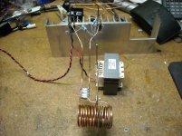
I'm using 11X .47uf 250V AC rated MKP caps in my tank circuit. They are all soldered to two copper plates that also have the FETs bolted directly to them. Two heatsinks and some ally bars are the bolted to the copper plates. The main source of heat in my lash up is the work coil, I have some small diameter copper tubing that I intend to use to make a water cooled work coil.
Cheers
Matt
https://markobakula.wordpress.com/power-electronics/500w-royer-induction-heater/
I use a separate regulated supply for the gates and a 24V 750VA control panel transformer with a 35A bridge and 40,000uf of filter capacitors.
You may notice that this circuit uses two chokes to decouple the oscillator from the supply. This allows a work coil without a centre tap.
I'm using 11X .47uf 250V AC rated MKP caps in my tank circuit. They are all soldered to two copper plates that also have the FETs bolted directly to them. Two heatsinks and some ally bars are the bolted to the copper plates. The main source of heat in my lash up is the work coil, I have some small diameter copper tubing that I intend to use to make a water cooled work coil.
Cheers
Matt
Nice clean work Matt with the integrated water cooling 
It is possible to solder FET tabs to copper heatsink, for an even lower thermal resistance, but it sounds like switching and conduction losses are well maintained for the FETs used with water cooling.
I guess the supply voltage could go lower (for those wanting to downsize power capability) by using appropriate logic level FETs ?
I can't imagine the RFC inductance is maintained at the nominal operating DC currents on those cores ??
Could always silver plate the coil !
More than 1 getter
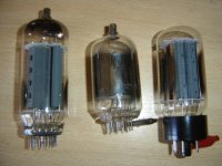
I have a couple of tubes, that have more than 1 getter, all of them are power tubes. Here are a photo of them.
http://www.diyaudio.com/forums/attachment.php?attachmentid=578804&stc=1&d=1478520936
From left to right: a 6KD6 hor. sweep (3 getters?) and sometimes used as linear amplifiers in ham radio, a 6KS6, and a 3DG4 rectifier.
Are necessary to have 3 getters?
Many thanks.
Attachments
- Home
- Amplifiers
- Tubes / Valves
- Re-activate getter/save gassy tube