Adding a a 200r resistor and 100uf cap to the op amp rails is improving the sound quality of the amp, no problem with that, anyway to improve sound quality is good.
Im wondering if it might be exposing a problem with the supply.
The supply is 2X15V trafo (measures 16V with amp playing) to +/-15V DC using LM317/337 regulators, 8800uf per rail with lots of low value bypass PP caps. With a cheap multimeter its measuring over 20V DC before the regulators, if there is ripple not sure if thats the min, max or average voltage.
ripple doesnt seem that likely anyway.
On an old post DF96 mentioned bypass cap resonance and how a RC circuit can filter this resonance, could that be the explanation here?
The choice of bypass caps was tested thoroughly, it was always better than without them but if it is introducing resonance does using an RC filter have any consequences?
You're wanting an explanation of how filtering an opamp's power rails improves the SQ?
What's your schematic? Do you have an opamp before a chipamp?
What's your schematic? Do you have an opamp before a chipamp?
Hi laserscrape,
The high capacitance is a complete waste, pretty silly actually. You may have some HF noise (likely) from the supply getting through the regulators. Your low pass filter is working. You should try to put it before the regulators, then make sure your bypass capacitors are still good. I normally use film capacitors in those locations, or at least for bypass if there are electrolytic capacitors used for bypass.
-Chris
Please define:
Hope it´s not just some "expectation bias" or some other uncontrolled phenomenon.
improving the sound quality of the amp
Hope it´s not just some "expectation bias" or some other uncontrolled phenomenon.
Could be, or he got rid of some hash. If that is the case, then putting the filter before the regulators should improve things I would think.
-Chris
-Chris
200R in series with an electrolytic doesn't sound like it would be all that effective tbh.
The regulator itself deals with short term transient changes in load and normally adding a large capacitance to the regulator output would totally negate that... although 200 ohms series R would not do anything imo, either good or bad.
Normally a small cap (say in the 1uF to 10uF range) might be used together with a series resistor of around a couple of ohms (a small 0.25watt carbon or metal film resistor).
Hi Karl,
Think in terms of high frequency filtering. Can't lose too much DC, so that limits R. You're only after high frequency components that active circuits have trouble with, so small-ish C. The regulators will do a bang-up job on the 120 Hz components and up a bit.
-Chris
Think in terms of high frequency filtering. Can't lose too much DC, so that limits R. You're only after high frequency components that active circuits have trouble with, so small-ish C. The regulators will do a bang-up job on the 120 Hz components and up a bit.
-Chris
A good thing to know would be whether or not the supply is only feeding opamps or some other circuitry. Heavy RC filters for opamps were common in philips cd players for example, where the rails were used for other uses (and sometimes not regulated at all).
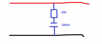
I think I misinterpreted the original question as I was thinking he meant this (image) as I latched onto the bit about resonance and assumed given that 8800uF was already present that something to address possible resonance issues was being called for.
So a cap in series with a low value resistor would have been one possible solution, just not 200 ohm 🙂
On an old post DF96 mentioned bypass cap resonance and how a RC circuit can filter this resonance, could that be the explanation here?
So a cap in series with a low value resistor would have been one possible solution, just not 200 ohm 🙂
Attachments
There are so many ways in which the OP's post can be interpreted we really need a simple diagram to understand it.
Say, for a start, for low currents, that 8800uF: presumably 4 x 2200uF caps - just adding some 1ohm between the caps could add immense filtering- but where & how are these caps used .. before or after the regulator? And why in either case?
Over to you, Laserscrape; help us help you.
Say, for a start, for low currents, that 8800uF: presumably 4 x 2200uF caps - just adding some 1ohm between the caps could add immense filtering- but where & how are these caps used .. before or after the regulator? And why in either case?
Over to you, Laserscrape; help us help you.
Hi Martin,
The problem is that those large capacitors, even at 2,200 uF, are very inductive at higher frequencies and they really don't do much for HF hash. So a small RF filter might just work wonders in there.
Although there are many ways to interpret the OP's post, we probably see the 8,800 uF in bulk capacitance after the rectifier. This likely feeds the adjustable regulators that knock it down to 15 VDC for the circuitry. See ...
He hasn't posted since 22nd May 2018 at 09:17 PM. I guess the post was a statement more than a question.
-Chris
The problem is that those large capacitors, even at 2,200 uF, are very inductive at higher frequencies and they really don't do much for HF hash. So a small RF filter might just work wonders in there.
Although there are many ways to interpret the OP's post, we probably see the 8,800 uF in bulk capacitance after the rectifier. This likely feeds the adjustable regulators that knock it down to 15 VDC for the circuitry. See ...
At first he said ...The supply is 2X15V trafo (measures 16V with amp playing) to +/-15V DC using LM317/337 regulators, 8800uf per rail with lots of low value bypass PP caps. With a cheap multimeter its measuring over 20V DC before the regulators, if there is ripple not sure if thats the min, max or average voltage.
ripple doesnt seem that likely anyway.
This would make a mighty odd zobel network. The resistor would be best in series with the power feed with the 100uF capacitor filtering on the op amp side.Adding a a 200r resistor and 100uf cap to the op amp rails is improving the sound quality of the amp, no problem with that, anyway to improve sound quality is good.
He hasn't posted since 22nd May 2018 at 09:17 PM. I guess the post was a statement more than a question.
-Chris
As Mooly said, we'd really need more info. It's very unclear if the OP meant using the 200r+200u as a zobel or as low pass filter on the rail. 😕
The question of resonnance leads to the first option but the values suggested lead to the second
The question of resonnance leads to the first option but the values suggested lead to the second
Could be, or he got rid of some hash. If that is the case, then putting the filter before the regulators should improve things I would think.
-Chris
Right! Or use capacitors that don’t have the issue with internal resonance also.
Hi phase,
LOL!
Can you imagine the size and cost of 8,800 uF worth of film capacitors? All larger electrolytic capacitors have poor characteristics at medium audio frequencies (> 1KHz), so to create a proper supply you have to either prevent diode switching noise to begin with, or use high audio and RF filters. Better yet, do both.
-Chris
...All larger electrolytic capacitors have poor characteristics at medium audio frequencies (> 1KHz)...
A modern snap-can has _lower_ impedance 1KHz to 500KHz than it does at any frequency below 1KHz. (I assume we do not play at -40C; this is an issue in industrial gear.) https://www.mouser.com/datasheet/2/88/SLP-15028.pdf
Yes, not a complete meal. Our amps often have response past 500KHz. And this curve is AT the cap terminals, where we normally need several inches of wire between fat-cap and actual circuit. So you do need physically small caps AT the amplifier, in addition to bulk caps. And since modern bulk-caps have VERY low internal loss, the whole thing becomes resonant in the MHz zone and some damping (resistance) may be needed.
Attachments
Hi PRR,
That is true. I'm using that type in all my new designs these days. But your normal leaded capacitors leave a lot to be desired in the HF department. But even the snap fit capacitors are heading for reduced performance b the time they see 100 KHz (graph you attached). For hash and noise we should be concerned above 100 KHz, certainly 1 MHz and a little higher. The AM band for sure as a lot of hash in that range.
-Chris
Ok to clarify some things:
the resistor is in series with supply and the cap goes to ground, so a low pass filter.
it is also feeding transistors in class A headphone amp, dont have an exact schematic but this can give a good idea if you ignore the power supply part: https://i.imgur.com/2g5Hoeg.png
its not expectation bias because I expected the amp to sound better without this filter once it was using a regulated supply, I assumed it was there for the basic original power supply that you can see in the schematic.
the caps are before the regulators, they are the filter caps after the rectifier.
Ill try adding the filter before the regulator instead
- Status
- Not open for further replies.
- Home
- Amplifiers
- Power Supplies
- RC filter on op amp rails improving sound quality?