ok. so. i have so much on my plate with this project ( some fool started with a single mini subwoofer project, and ended up trying to build a pair of cnc cut translam dual driver fullrange speakers with matching subwoofers, and a six channel amp with built in minidsp.)
i think i will finish building the damn thing and listen to it. if i feel i need a single point source for the treble, i will revisit the amp input filtering. i started researching unity-gain buffers, then thought.. maybe it can wait. 🙂
i think i will finish building the damn thing and listen to it. if i feel i need a single point source for the treble, i will revisit the amp input filtering. i started researching unity-gain buffers, then thought.. maybe it can wait. 🙂
i had another thought: would it be possible to add the capacitance after the input resistors of the power amp, or even after the entire input stage? that way the op-amp would act as buffer, and remove the necessity to add another buffer in the signal path..?
i was looking at the schematic, but with my limited skills and the added complexity of the SE/Differential switching, i was unable to suggest a suitable location to add a lowpass cap. (if it helps, the jumpers are set to "differential")
i was looking at the schematic, but with my limited skills and the added complexity of the SE/Differential switching, i was unable to suggest a suitable location to add a lowpass cap. (if it helps, the jumpers are set to "differential")
Attachments
i had another thought: would it be possible to add the capacitance after the input resistors
of the power amp, or even after the entire input stage? that way the op-amp would act as buffer,
and remove the necessity to add another buffer in the signal path..?
The source impedance would still have the same effect for an amplifier input filter.
It would be buffered if the filter were in a later stage.
Sometimes, "power" crossovers might have some sense 😛
After the amplifier, you have two FR speakers and you want only one to emit treble ( or to not emit bass ).
With parallel crossover connection, one driver will be wired as in 1.5 way, so a low pass ( inductance ) on one.
With series connection, you'll have the drivers in series and one capacitor across one
Ahh haha i was waiting for someone to suggest that. Theres another whole thread that led to this solution. The amp is configurable as a stereo amp (2x btl) or a quad channel Single ended config, or a 3 channel amp 1xbtl, 2x se. I have one of these boards for each channel. Originally i was going to leave it at 2x btl, with one channel for the sub, and one channel driving the dual fullrangers with a setup as you describe.
However there were stability issues with driving a 16 ohm load ( two 8 ohms in series) and i was advised that was preferable to parallel. somebody then said "why dont you do a single amp channel for each driver, youve got the channels. then you dont have that issue and you can do a dead simple r/c circuit to lowpass one amp" which sounded much more elegant and simpler than the fixes necessary to run 16 ohm speakers with the amp (post filter feedback) . Nothing is ever so simple eh? Ill link the thread when i have time and im at home.
However there were stability issues with driving a 16 ohm load ( two 8 ohms in series) and i was advised that was preferable to parallel. somebody then said "why dont you do a single amp channel for each driver, youve got the channels. then you dont have that issue and you can do a dead simple r/c circuit to lowpass one amp" which sounded much more elegant and simpler than the fixes necessary to run 16 ohm speakers with the amp (post filter feedback) . Nothing is ever so simple eh? Ill link the thread when i have time and im at home.
The source impedance would still have the same effect for an amplifier input filter.
It would be buffered if the filter were in a later stage.
Im not sure i follow your reply, sorry! My thinking was, if i place the capacitor after the 10k resistor on the amp input stage, that would be better with regards to isolating the lowpass from affecting the other amp, and id be using the 10k (plus the 560R output impedance of the minidsp) as the R in my RC network.
Then i thought if i lowpassed after the input opamp there, id have proper isolation of the other amp from the lowpass... However, even if that is the case, i have no idea if there is a sensible spot in that schematic to drop a capacitor in, without having to add extra resistance and reducing the gain.
If they are connected, then they can't be isolated.
Isolated means they are NOT connected.
Ok yep. Hands up. Entirely wrong term to use. Im referring to the effect of the lowpass filter, which, without some kind of buffer, will affect both amps, since they are connected in parallel. Placing the cap after the 10k resistors would (to my mind) negate the need to add extra resistance for the r/c filter thus avoiding reduced gain, and place 20kohms of resistance between the filter cap, and the other amp. No idea if that would be sufficient to avoid killing the treble percievably.
Placing the lowpass after the opamp on the amp input (seems to me) the same effect as adding an extra buffer opamp, which was the suggested course of action to completely avoid the lowpass affecting the other amp. However as noted, im a noob and am scrounging round for expert advice 🙂
yes post 42, and as it states in that post, im not sure of the correct location, if there is one. i was basically asking if the general idea is a good one or not.
i know enough to propose an idea, but not enough to generate a solution.
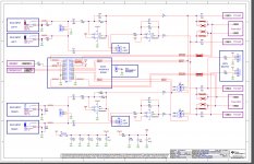
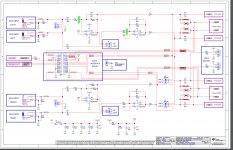
one suggestion was to add lowpass caps from the locations marked green on the attached mark-up (obviously connected from that point to signal ground (or maybe some other point? ) that way the 10kohm input resistors would form the resistance in the RC filter and remove the necessity to add extra resistance to the signal path.
beyond that, my suggestion to add them *after* the op-amps, if we look at the second page of the schematic (also attached, area of interest shaded green) there is already what appears to be a lowpass filter in there, but if its 100 ohms and 100pf, then thats a 15 mhz lowpass. maybe i could modify that?
i know enough to propose an idea, but not enough to generate a solution.
one suggestion was to add lowpass caps from the locations marked green on the attached mark-up (obviously connected from that point to signal ground (or maybe some other point? ) that way the 10kohm input resistors would form the resistance in the RC filter and remove the necessity to add extra resistance to the signal path.
beyond that, my suggestion to add them *after* the op-amps, if we look at the second page of the schematic (also attached, area of interest shaded green) there is already what appears to be a lowpass filter in there, but if its 100 ohms and 100pf, then thats a 15 mhz lowpass. maybe i could modify that?
Attachments
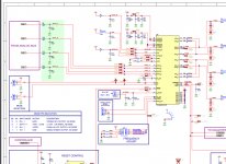
for example if i added a 500nF capacitor in parallel with that 100pf one ( easier than swapping, its a 603 smt component) i should (if my studying has paid off) get a lowpass of 3.18khz there, instead of the current 15mhz one.
A low pass filter is just an RC for a single pole roll off.
For better RF attenuation and minimum spray of emi from the internal cabling the RF filtering should be right at the enclosure entry.
This places the R direct to the Hot input pin and the C then connects the output of that R to the Cold pin. For audio you could use an RC of 1us to 2us (100r & 10nF = 1us, or 1k & 1nF, or 10k & 100pF)
The higher the R value the more noise and more more attenuation of the signal. The higher the capacitance the more the inductance and thus less extreme RF attenuation like at 1GHz to 10GHz.
If you want to put the RF filtering later in the assembly, then you could put it at the 100k Rin, or much later just after the 10uF+10k. But the later you place this, the more cabling is exposed to the unfiltered emi.
All the preceding is for differential filtering by returning the interference back to the signal return wiring.
For common mode filtering you would place the C components from the line to the enclosure. This is eaiset achieved at the input socket. A connection direct to the grounded shell of the XLR socket or direct to pin1 that in turn is directly connected to the enclosure.
Both lines need the common mode filtering.
If you are in a high emi environment then ALL the inputs to the enclosure need common mode filtering, i.e the power lines and the output lines all get capacitively coupled to the enclosure at their entry points.
You have shown a green triple bar GND symbol all around your schematic. Do you have any idea if they are power ground, PSU zero Volts, or Signal ground or Chassis, or Safety Earth?
You need to look at each one and decide where exactly each needs to go. I counted 43 GNDs, I'll bet they are NOT all the same.
Last edited:
I don't know what bandwidth the MUX output needs to send to inputs A, B, C & D.for example if i added a 500nF capacitor in parallel with that 100pf one ( easier than swapping, its a 603 smt component) i should (if my studying has paid off) get a lowpass of 3.18khz there, instead of the current 15mhz one.
Do you know?
Why did they insert a 16MHz filter there?
that schematic is the one provided by TI for the 3255 evaluation board i am using.
the lowpass filter i require isnt for RF supression, its to provide a gentle roll-off above 3 khz or so for the lower frequency fullrange in a 1.5 way dual fullrange speaker setup..
im just looking for a place to put the lowpass where it will not attenuate the signal noticably or cause reduction in frequency response in the other amp (connected in parallel to same signal source, not low-passed)
maybe ive not understood your reply, but you are talking about rf filtering and it seems despite repeated descriptions and many posts, ive not managed to even explain my aim, or even the basic project configuration!
I don't know what bandwidth the MUX output needs to send to inputs A, B, C & D.
Do you know?
i would imagine its a typical audio bandwith...?
Why did they insert a 16MHz filter there?
i have no idea.. rf supression?
entire schematic is here:
http://www.ti.com/lit/df/slar129a/slar129a.pdf
user guide is here:
http://www.ti.com/lit/ug/slou441/slou441.pdf
http://www.ti.com/lit/df/slar129a/slar129a.pdf
user guide is here:
http://www.ti.com/lit/ug/slou441/slou441.pdf
hm, err. ok. well before you go could you at least give your opinion as to wether, looking at that schematic, adding a 500nf capacitor there (where the 100pf one is currently) would indeed cause the signal there to be attenuated above circa 3.2 khz? thats all im really asking... and wether id risk causing other issues by testing it?
ive spent many many (many) posts trying (quite clearly i thought) to explain what i want to achieve... at least i could win an opinion at the end? you obviously know what you are doing.
ive spent many many (many) posts trying (quite clearly i thought) to explain what i want to achieve... at least i could win an opinion at the end? you obviously know what you are doing.
- Status
- Not open for further replies.
- Home
- Source & Line
- Analog Line Level
- RC filter component selection