Chilkook, what were you told about the design of this amp? Can you post photos
of the IC and the transistors (showing the part numbers). Perhaps it's an
LME498XX based design?
of the IC and the transistors (showing the part numbers). Perhaps it's an
LME498XX based design?
I initially thought it was a dual JFET, 2SK389, in an AB100 like amp but too many pins. Overall layout looks similar to NPs 100W AB amp ..dB
This “professional” has been making money with Papa’s intellectual property for a long time.....
“After” pix of the amp in post #1. I need to take all the detailed measurements and give it a long warm up and burn in session. After the rebuild tonight the sound was great, and there was no hum/noise.
Attachments
-
 0F6F9C9C-84A0-42C5-BD72-B55F3C75F0D6.jpeg305.9 KB · Views: 405
 -
 BF921431-C528-4864-992A-394E8149F19C.jpeg459.5 KB · Views: 390
 -
 B28FAE1D-AFB8-402D-874B-9DA2C7AD082D.jpeg496.7 KB · Views: 295
 -
 8B08B5F5-81F2-4172-8CC4-BF3307090652.jpeg479.7 KB · Views: 281
 -
 ADC3136D-D624-4666-A665-57CCF623504C.jpeg386.7 KB · Views: 290

More info on the rawson
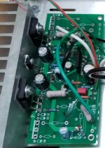
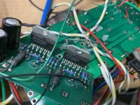
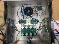
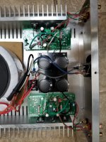
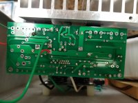
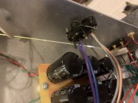
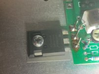
I took a few more photos, and looked at the parts to identify. The power devices are marked IRFP240, and the amplifiers are LME49830. I can't see any text on the pcbs to indicate what the design is, and don't know what the circuit or design is.
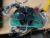
The power supply pcb is really crap. If possible, I would like to make it at least safe!
I took a few more photos, and looked at the parts to identify. The power devices are marked IRFP240, and the amplifiers are LME49830. I can't see any text on the pcbs to indicate what the design is, and don't know what the circuit or design is.
The power supply pcb is really crap. If possible, I would like to make it at least safe!
Attachments
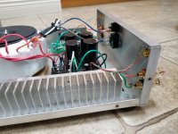

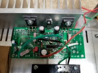
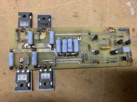
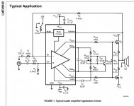
Look at page 2 of the LME49830 datasheet. This looks very close to the typical application design. (A good thing)
LME49830 pdf, LME49830 description, LME49830 datasheets, LME49830 view ::: ALLDATASHEET :::
LME49830 pdf, LME49830 description, LME49830 datasheets, LME49830 view ::: ALLDATASHEET :::
Attachments
Last edited:
Next project that I’ll be doing is a Rawson Built F2J. Kinda cool because when it’s done I’ll let it give my SissySIT a break before I ship this back to the owner.
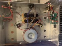
No grounding. Classic.
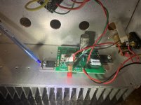
Psu appears to be CRCRC single rail. Different caps.
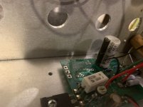
Amp PCBs are mystery PCBs that appear to be cut somehow. Gotta give MacGuyver points for such implementation
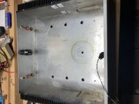
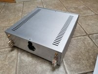
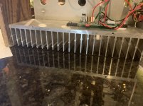
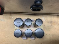
I like the design on the heat sink, it’s a bit unusual.
I’m going to measure voltage, gain, offset, etc. and make an “as-built” schematic before making a final plan. After measuring I’ll also see what the bottom of the psu board looks like.
Initial thoughts of what to do on this amp include adding proper grounding and upgrading the power supply including snubbers. I’ll decide what to do on amp boards after I confirm all the details.
No grounding. Classic.
Psu appears to be CRCRC single rail. Different caps.
Amp PCBs are mystery PCBs that appear to be cut somehow. Gotta give MacGuyver points for such implementation
I like the design on the heat sink, it’s a bit unusual.
I’m going to measure voltage, gain, offset, etc. and make an “as-built” schematic before making a final plan. After measuring I’ll also see what the bottom of the psu board looks like.
Initial thoughts of what to do on this amp include adding proper grounding and upgrading the power supply including snubbers. I’ll decide what to do on amp boards after I confirm all the details.
Attachments
-
 97112EFD-ACF5-4697-9B83-EF5F305267D0.jpeg310.1 KB · Views: 371
 -
 7CA81653-01D5-49FE-AC06-5380EDFBF853.jpeg254.3 KB · Views: 354
 -
 46EAD54B-29CD-4CAB-AA16-3FD5E436C483.jpeg406.7 KB · Views: 353
 -
 BACD648D-E549-4BC0-B6B2-9063054D42CA.jpeg348.1 KB · Views: 357
 -
 39DBE501-78E3-4D7A-829F-ACE7E0E7FA4A.jpeg281.4 KB · Views: 256
 -
 DCFE4C55-6049-4883-8A1F-8AC4FE4C67FF.jpeg321.4 KB · Views: 274
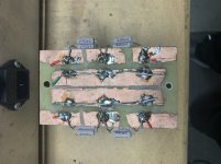
It actually looks like a fair bit of work to remove all that copper. I would have
thought a simple perf board would be both quicker and neater.
thought a simple perf board would be both quicker and neater.
- Home
- Amplifiers
- Pass Labs
- Rawson Repair Reflections