Hi all,
I am trying to repair a Hameg 412 Oscilloscope from 1976 🙂
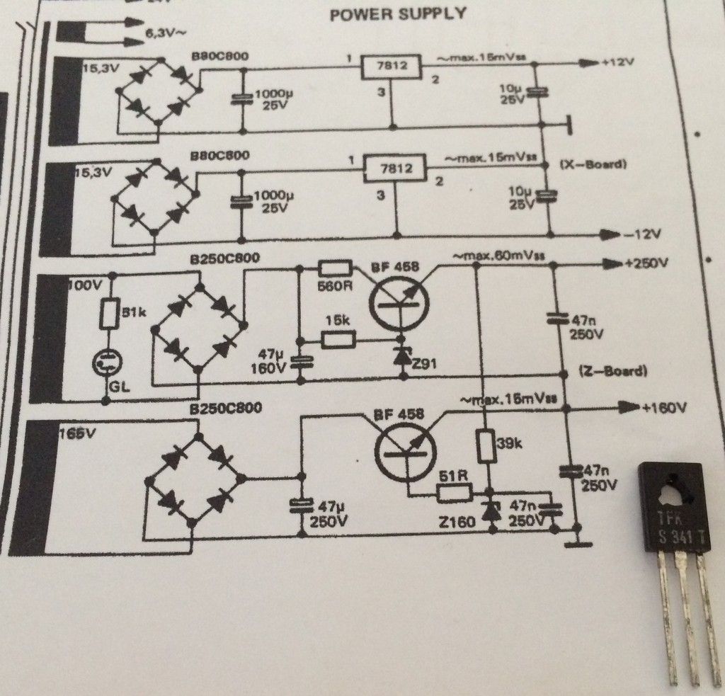
The power supply uses 2 telefunken power transistors TFK S 341T in order to deliver 250V & 160V.
I have found out that one transistor has failed along with a 160V zener diode.
Unfortunately I can not find a replacement transistor .... 🙁
I checked the service manual, but the schematics show different transistors (BF458) with slightly different component orientation . ( there is no 51R resistor and no 47nf capacitor)
I have tried replicating the schematics found in the service manual and used 2 x BF458 but I am getting slightly wrong voltage (268V & 168V)
here is a picture of the transistor and the schematics :
Does anybody know of a replacement transistor of TFK S 341T ?
Any help would be highly appreciated ,
thanks
I am trying to repair a Hameg 412 Oscilloscope from 1976 🙂
The power supply uses 2 telefunken power transistors TFK S 341T in order to deliver 250V & 160V.
I have found out that one transistor has failed along with a 160V zener diode.
Unfortunately I can not find a replacement transistor .... 🙁
I checked the service manual, but the schematics show different transistors (BF458) with slightly different component orientation . ( there is no 51R resistor and no 47nf capacitor)
I have tried replicating the schematics found in the service manual and used 2 x BF458 but I am getting slightly wrong voltage (268V & 168V)
here is a picture of the transistor and the schematics :
Does anybody know of a replacement transistor of TFK S 341T ?
Any help would be highly appreciated ,
thanks
It won't be the difference in transistor used because an NPN transistor with reasonable gain is an NPN transistor with high enough CE voltage. Check the voltage on the zeners, you will have about 1Volt less on the outputs.
TIP50
https://www.fairchildsemi.com/datasheets/TI/TIP50.pdf
MJE340
http://www.onsemi.com/pub_link/Collateral/MJE340-D.PDF
Most TO-126 Transistor pinouts are 1,2,3=ECB
https://www.fairchildsemi.com/datasheets/TI/TIP50.pdf
MJE340
http://www.onsemi.com/pub_link/Collateral/MJE340-D.PDF
Most TO-126 Transistor pinouts are 1,2,3=ECB
Thank you all for your help !
I have replaced both zener diodes but nothing changed,thats why I thought that there should be a transistor mismatch.
many thanks, how did you find these ?
I could not even find a datasheet for the TFK S 341T, I had no idea what specs I was looking for.
Are these direct replacements or do I have to change some components in the circuit?
So you think that sth other than the transistors is causing the wrong voltage?It won't be the difference in transistor used because an NPN transistor with reasonable gain is an NPN transistor with high enough CE voltage. Check the voltage on the zeners, you will have about 1Volt less on the outputs.
Z91 = 250V zener and Z160 = 160V zener.
I have replaced both zener diodes but nothing changed,thats why I thought that there should be a transistor mismatch.
jackinnj said:TIP50
https://www.fairchildsemi.com/datasheets/TI/TIP50.pdf
MJE340
http://www.onsemi.com/pub_link/Collateral/MJE340-D.PDF
Most TO-126 Transistor pinouts are 1,2,3=ECB
many thanks, how did you find these ?
I could not even find a datasheet for the TFK S 341T, I had no idea what specs I was looking for.
Are these direct replacements or do I have to change some components in the circuit?
Last edited:
Well I have just used 2 x TIP50 but I get the same wrong voltage ,as with the BF458.
It seems that the problem lies elsewhere.
Could it be that the transistors need matching ?
Any ideas ?
Thanks
It seems that the problem lies elsewhere.
Could it be that the transistors need matching ?
Any ideas ?
Thanks
Hi,
One easy way to find where is the problem it is checking the base voltage. If the zener it is working OKAY it should read 160volts and 260volts.
One easy way to find where is the problem it is checking the base voltage. If the zener it is working OKAY it should read 160volts and 260volts.
No, Z91 is a 91V zenerZ91 = 250V zener and Z160 = 160V zener.
The two zeners are effectively in series for the 250V output.
Zeners can have a large tolerance and high voltage types don't have a very sharp knee either
The 51R resistor is to stop the bottom transistor oscillating at rf, which might cause the voltage shift
Last edited:
thank you both your input.
The base gives me the same erroneous voltage, so I went out and bought a few new zeners for testing purposes.
I removed the 51R resistor but there was no voltage change.
Yes there is a load , if I am not mistaken ,the 160V drive the vertical final stage and the 250V provide power for the Horizontal amplifier.
Could it be the bridge rectifiers ? hmm I doubt it ...
I suspect that the problem lies somewhere else in the circuit and as a result the power supply does not work on full load thus the transformer outputs higher voltage than normal. I tested the transformer and it outputs a few volts higher than it should. ( 174Vac instead of 165Vac and 105Vac instead of 100Vac)
I cant think of anything else , this thing gives me a headache, any advice/help will be deeply appreciated .
Hi,
One easy way to find where is the problem it is checking the base voltage. If the zener it is working OKAY it should read 160volts and 260volts.
The base gives me the same erroneous voltage, so I went out and bought a few new zeners for testing purposes.
I had no idea that zeners had large tolerance ,so I tested a few others and I had a bit of voltage drop (1-2V) , but the voltage is still out of specs.Zeners can have a large tolerance and high voltage types don't have a very sharp knee either
The 51R resistor is to stop the bottom transistor oscillating at rf, which might cause the voltage shift
Also is the 160V loaded? This circuit does need a load
I removed the 51R resistor but there was no voltage change.
Yes there is a load , if I am not mistaken ,the 160V drive the vertical final stage and the 250V provide power for the Horizontal amplifier.
Could it be the bridge rectifiers ? hmm I doubt it ...
I suspect that the problem lies somewhere else in the circuit and as a result the power supply does not work on full load thus the transformer outputs higher voltage than normal. I tested the transformer and it outputs a few volts higher than it should. ( 174Vac instead of 165Vac and 105Vac instead of 100Vac)
I cant think of anything else , this thing gives me a headache, any advice/help will be deeply appreciated .
Last edited:
Yes , actually I am using the 47nf/250V capacitor as a check point for all 160v/250v measurementsHi,
Can you read both voltages at the capacitor?
Could it be that the original TFK S 341T drew more load, making the transformer output less voltage ?
Is there a way to regulate the voltage down to specs (obviously by adding/removing components), so that I can troubleshoot the rest of the circuit properly ?
Any ideas?
Hi,
What I mean was to read the voltage and post the reading. What I want it is to see the voltage before and after the transistors.
What I mean was to read the voltage and post the reading. What I want it is to see the voltage before and after the transistors.
You probably have high mains.
Zeners are calibrated at test current. This design matches typical 3W zeners, 4mA @91V and 2.3mA @160V. What part number have you been using?
Increasing the zener feeds 15k to 22k and the 39k to 47k would drop the voltages a little
Zeners are calibrated at test current. This design matches typical 3W zeners, 4mA @91V and 2.3mA @160V. What part number have you been using?
Increasing the zener feeds 15k to 22k and the 39k to 47k would drop the voltages a little
Zeners typically have a 5% to 10% tolerance, are somewhat temperature sensitive and their threshold voltage also varies significantly if the zener current is different than the manufacturer specified measurement current.
It is not likely to be all that critical. (As long as it is consistent)
It is not likely to be all that critical. (As long as it is consistent)
Sorry Tauro , I will post the reading later today, as soon as I get home.Hi,
What I mean was to read the voltage and post the reading. What I want it is to see the voltage before and after the transistors.
Thanks for the info.You probably have high mains.
Zeners are calibrated at test current. This design matches typical 3W zeners, 4mA @91V and 2.3mA @160V. What part number have you been using?
Increasing the zener feeds 15k to 22k and the 39k to 47k would drop the voltages a little
I have no way of telling what were the specs of the original diodes, in the schematics it just say Z160 and Z91. I have just used generic 3watt BZX 160 & BZX 91 that I could find locally. I will try some resistor tweaking and see if i can get the voltage to drop a bit.
Zeners typically have a 5% to 10% tolerance, are somewhat temperature sensitive and their threshold voltage also varies significantly if the zener current is different than the manufacturer specified measurement current.
It is not likely to be all that critical. (As long as it is consistent)
Hmm, so if sth draws more current, the voltage threshold could change... But if the load is increased , the zener voltage should drop ( not increase, as in my case ) , right ? At least thats what I remember when i was fiddling with simple 5v zener psus.
Please bare with me, although I am familiar with common linear PSUs, transistor and zener based PSUs are new to me.
Last edited:
Low beta transistors would steal current from the zeners, reducing the voltages. What might be worth trying is replace the 160V zener with two 75Vs in series or a 75V+82V, lower voltage and better regulation, 160V zeners have a very poor VI curve
Hi,
The reason I have been asking for the voltages it is because if you know the voltage you can divide it by the resistor and see if the current comply with the minimum current that the zener need to control the voltage. If not the zener will not regulate/control the voltage. voltage / 18K = current.
The reason I have been asking for the voltages it is because if you know the voltage you can divide it by the resistor and see if the current comply with the minimum current that the zener need to control the voltage. If not the zener will not regulate/control the voltage. voltage / 18K = current.
Excellent idea David ! I was not aware that I can combine zeners ...Low beta transistors would steal current from the zeners, reducing the voltages. What might be worth trying is replace the 160V zener with two 75Vs in series or a 75V+82V, lower voltage and better regulation, 160V zeners have a very poor VI curve
I am going Zener shopping tomorrow ,first thing in the morning !
thank you for your support Tauro, I deeply appreciate it.Hi,
The reason I have been asking for the voltages it is because if you know the voltage you can divide it by the resistor and see if the current comply with the minimum current that the zener need to control the voltage. If not the zener will not regulate/control the voltage. voltage / 18K = current.
With reference to ground the upper filter cap ( 47uf/160v) reads 309 V on the positive side and 171.5 on the negative. The voltage difference is 137.5, so divided by 15k the current is 0,00916 amperes = 9.16mA
I checked the BZX 160 datasheet which is found here , I am not sure to which characteristic I should compare to. Can you please clarify this ?
This Oscilloscope belonged to a good friend that recently passed away. It is a matter of personal honor to repair it, so i would like to thank everybody who is helping me in this.
Just for fun , here are some pics of it:
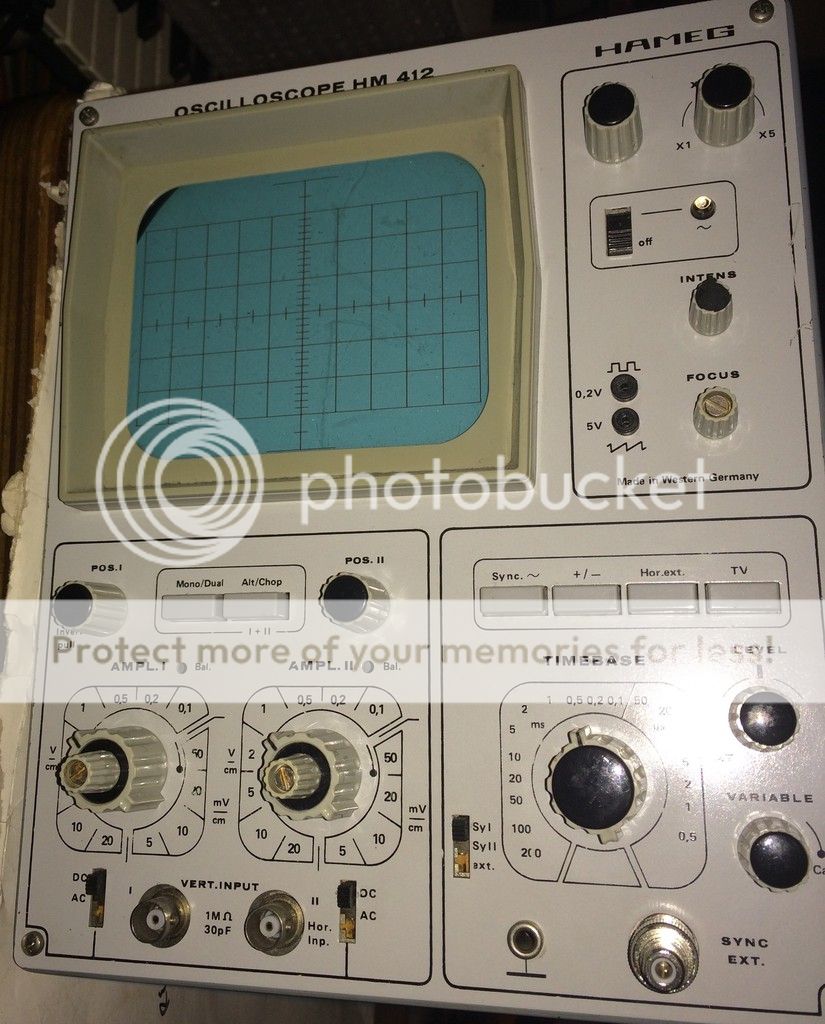


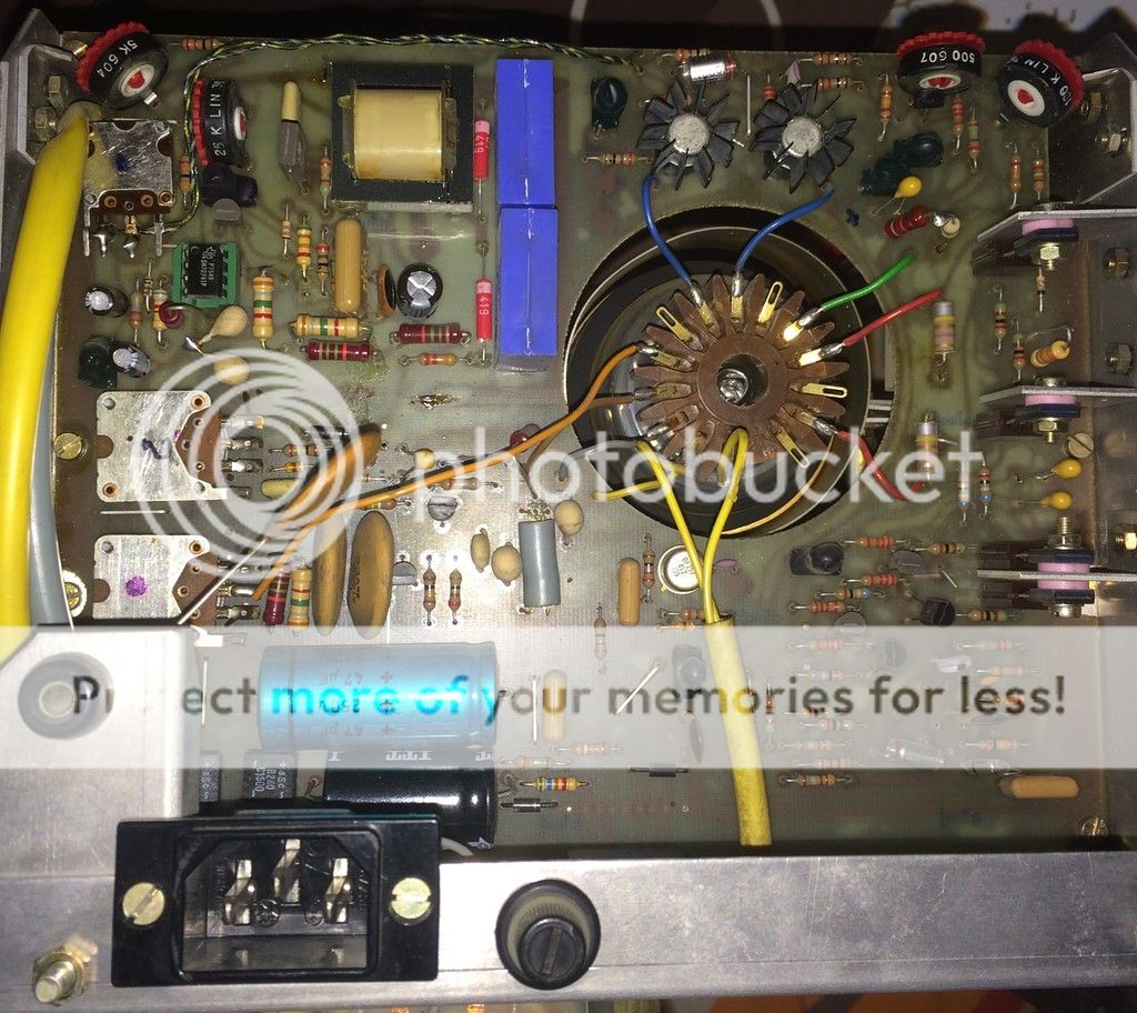
It is a Hameg 412-1 made in (Western) Germany in 1975.
Last edited:
The BZX55 is a 1W part and calibrated at lower currents than the Hameg circuit. This would explain your high voltages.
The poor performance of high voltage zeners is why most ranges max at 75V. Your data sheet shows <6k5 for the 160V part, so just 1mA extra raises the nominal voltage by up to 6.5V
It is common to use 2 or 3 lower voltage zeners in series for a high voltage as they are cheap. The voltages simply add.
- Status
- Not open for further replies.
- Home
- Design & Build
- Parts
- Rare transistor replacement / Oscilloscope repair