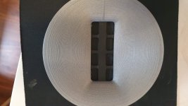
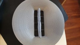
No teardown photos this time, but here are a few response plots of two Radian LT3 drivers I got. I've also attached the 3D model for the waveguide.
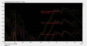
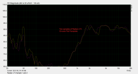
I think these drivers internally must be very similar to the Neo3, only with bigger magnets and fewer but larger holes on the front. There is a striking similarity to the two dips in the response of Neo3 drivers at about 3KHz and 7KHz.
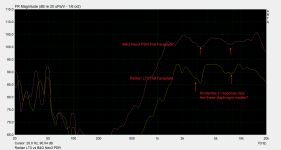


I think these drivers internally must be very similar to the Neo3, only with bigger magnets and fewer but larger holes on the front. There is a striking similarity to the two dips in the response of Neo3 drivers at about 3KHz and 7KHz.

Attachments
Faaaak curiosity killed the bank account, I just had to see inside but my gosh those magnets are strong!
Apparently no damping inside the case, even in the back - only in the rear chamber.
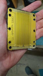
Weird pattern on the 'in-active' top and bottom of diaphragm - have they folded it over to reduce space used for the traces that link the 'active' traces on the diaphragm??
Like the LT2, pretty creases in the diaphragm and no etching away of unused metal.
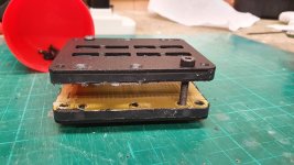
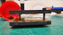
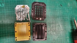
(Neo3 for reference)
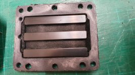

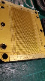
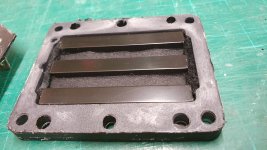
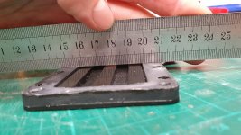
(0.75mm gap)
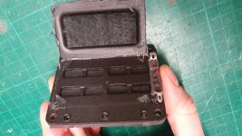
Whoops during re-assembly!
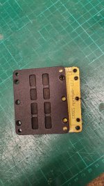
Apparently no damping inside the case, even in the back - only in the rear chamber.
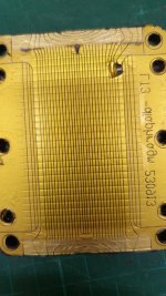
Weird pattern on the 'in-active' top and bottom of diaphragm - have they folded it over to reduce space used for the traces that link the 'active' traces on the diaphragm??
Like the LT2, pretty creases in the diaphragm and no etching away of unused metal.


(Neo3 for reference)


(0.75mm gap)


Whoops during re-assembly!


Cool thanks ! saves me buying one 🙂 i was wondering 🙂
Could you measure the magnets ? i know you sort of did but it is really hard to make up what they actually are.to bad they put the felt in between or behind the magnets..its a missed change of having more damping with less felt, hence less losses in the top end.
Foil looks nice, not sure if the corugation does much, when they are crossed at 1.2khz... usually corugation is usefull to reach a lower resonance but im not sure where the resonance would be in this case. could you measure that ?
so no crossover and measure at low volume close to the tweeter to not burn them up 🙂
Magnets are 8mm x 60mm, 4mm thickness. 8mm spacing between them.
Difficult to say about resonance, I think what we see here is mainly cavity resonance due to the matching with those big dips in the response. Perhaps the very slight rise around 1KHz is the main tuning freq. of the diaphragm?
By my judgment I would say the narrower opening on this LT3 compared with BG Neo3 helps match the on and off axis response better. However it also makes those dips at 3KHz and 7KHz stronger. Probably a sensible compromise if you have a system with DSP, but not so great for passive.
Difficult to say about resonance, I think what we see here is mainly cavity resonance due to the matching with those big dips in the response. Perhaps the very slight rise around 1KHz is the main tuning freq. of the diaphragm?

By my judgment I would say the narrower opening on this LT3 compared with BG Neo3 helps match the on and off axis response better. However it also makes those dips at 3KHz and 7KHz stronger. Probably a sensible compromise if you have a system with DSP, but not so great for passive.
Last edited:
i think resonance is more like 800Hz or lower especially with the corrugation. to me the look to be mostly aimed at efficicency. not at all at smooth response 🙁 increacing magnet size wil only upp the efficiency and degrade the frequency response 🙁
for normal speaker you can get away with push pull without any metal and thinner magnets like i do, and you get a far smoother response without the need of eq. this is not one of them im afraid
Well.. on and off axis are more matched than neo3, so a benefit there. If you EQ the output flat it looks nicer than neo3 with lower distortion too. High frequency is more narrow though.
WrineX are you Joppe Peelen?
WrineX are you Joppe Peelen?
That sounds weird to say , but i am Joppe Peelen yeps 🙂 always used wrinex in the past for everything and joppe peelen lately on my youtube.Well.. on and off axis are more matched than neo3, so a benefit there. If you EQ the output flat it looks nicer than neo3 with lower distortion too. High frequency is more narrow though.
WrineX are you Joppe Peelen?
I myself like a tweeter that goes a little lower over dispersion in a frequency range i cant hear anyway 🙂 but there are valid reasons for both 🙂 the LT uses such a thick membrane i cant imagine it will be flat above 16 khz to begin with 🙁 the neo on the other hand has a lighter foil , but also a cavity resonance.
i made some smaller tweeters on my channel, but did not put my eggs in the efficiency basket. since i got no uses for it. besides wasting money on resistors 🙂
i often go for single ended because of this reason. it will increase THD but thats mostly second order. that we cant hear that well to start with. while 3th harmonics usually stay very low. and frequency response is smoother.
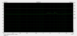
by the way thats some rather high impedance peaks for a planar in the middle of the working region. never seen that. i guess some resonances there?
The LT3 is really much thicker foil than the smaller LT2 (120micron). It doesn't say the thickness but it feels very strong.
The LT2 which says 120micron actually feels more delicate than the BG diaphragm. I guess the corrugation creases allows movement even though it is a thick material.
The impedance spike at ~3KHz matches with a big dip in frequency response - I think that is the cavity created by the front and back metal plates.
The impedance spike at ~1.5-2KHz I guess is due to the rear chamber which is quite small.
I wanted to ask you what function the metal plate that holds magnets has, generally in a planar? Is it only to hold the magnets or does it do an important job for the magnetic field? I know that it will short the magnetic field on the back of the magnets and that helps to stop accidents near the driver with metal parts.
I found your YouTube a couple day ago. You have a lot of videos! Can you recommend the best ones to learn how to make the diaphragm?
Ai i cant say i have a video in mind that explains what i do, halve the time i dont... 🙂 it has become sort of a mess. 350+ videos, mostly you can ignore the ones with TUNE in them. i do ethcing variants as well as plotting. i find plotting the easiest and cheapest. with the most options of alu thickness and or mylar/kapton etc.The LT3 is really much thicker foil than the smaller LT2 (120micron). It doesn't say the thickness but it feels very strong.
The LT2 which says 120micron actually feels more delicate than the BG diaphragm. I guess the corrugation creases allows movement even though it is a thick material.
The impedance spike at ~3KHz matches with a big dip in frequency response - I think that is the cavity created by the front and back metal plates.
The impedance spike at ~1.5-2KHz I guess is due to the rear chamber which is quite small.
I wanted to ask you what function the metal plate that holds magnets has, generally in a planar? Is it only to hold the magnets or does it do an important job for the magnetic field? I know that it will short the magnetic field on the back of the magnets and that helps to stop accidents near the driver with metal parts.
I found your YouTube a couple day ago. You have a lot of videos! Can you recommend the best ones to learn how to make the diaphragm?
the metal is used to connect one north pole of a magnet to the next south pole of the next magnet. so a magnetic circuit. increasing there output. but often the increase is far lower then modeled, since halve of the metal in between magnets has huge holes cut out 🙂 so i think it is mostly practical and still adds a dB or more. i opt for no metal often for easy of construction and les cavity res problems but then again you have slightly less output and are bound to magnet sizes you chose. also if i would use such big ones i might have a very hard time to do it without metal 🙂 when you want push pull.
Last edited:
Thanks that is very interesting! I wonder if the small 'bridges' between the magnets in a Neo3 or in the LT2 really allow much flowing of the magnet field.
I was hoping to remove the front metal and hold the magnets directly in the waveguide, so it can be closer to the diaphragm. I think you know Paul of Polymate3D, I will ask him to do a magnetic simulation and see what effect that metal is having 🙂
I was hoping to remove the front metal and hold the magnets directly in the waveguide, so it can be closer to the diaphragm. I think you know Paul of Polymate3D, I will ask him to do a magnetic simulation and see what effect that metal is having 🙂
Yeah i do know Paul good fellow ! yeah if you have enought ouput in single ended it should work fine, it worked for me at least. as long as you dont need that extra ouput or do not care all that much about more 2e order hamrnonicsThanks that is very interesting! I wonder if the small 'bridges' between the magnets in a Neo3 or in the LT2 really allow much flowing of the magnet field.
I was hoping to remove the front metal and hold the magnets directly in the waveguide, so it can be closer to the diaphragm. I think you know Paul of Polymate3D, I will ask him to do a magnetic simulation and see what effect that metal is having 🙂
Hi!
How this driver sounds If EQ-ed to flat? The resonances (which are visible on the impedance curve) are bad? The datasheet claims it sounds more transparent than other conventional (assuming typical drivers with voice-coil?) high-frequency drivers. Is that would be true?
How this driver sounds If EQ-ed to flat? The resonances (which are visible on the impedance curve) are bad? The datasheet claims it sounds more transparent than other conventional (assuming typical drivers with voice-coil?) high-frequency drivers. Is that would be true?
Hi!,
Just out of curiosity, how did you go about designing that waveguide? the increase in SPL that it gave is quite substantial. I've been thinking of building something like that for a GRS Neo 3 driver.
Just out of curiosity, how did you go about designing that waveguide? the increase in SPL that it gave is quite substantial. I've been thinking of building something like that for a GRS Neo 3 driver.
No teardown photos this time, but here are a few response plots of two Radian LT3 drivers I got. I've also attached the 3D model for the waveguide.
View attachment 1050378
View attachment 1050385
View attachment 1050379View attachment 1050381
I think these drivers internally must be very similar to the Neo3, only with bigger magnets and fewer but larger holes on the front. There is a striking similarity to the two dips in the response of Neo3 drivers at about 3KHz and 7KHz.
View attachment 1050384
I used a command line program called ATH (search it here there is a BIG thread) and imported the profile curve in to Fusion360 with the script they supply.Hi!,
Just out of curiosity, how did you go about designing that waveguide? the increase in SPL that it gave is quite substantial. I've been thinking of building something like that for a GRS Neo 3 driver.
once I had the profile curve I used a loft between the inside rectangle shape and the outside circle shape while using the ATH profile curve as 'rails' for the loft.
If you like, you can then export the surface as a STEP file, create a mesh in GMSH and simulate the acoustics in AKABAK.
I did think of doing a video on that process. It was a steep learning curve!
Sorry I only measured it. However I love the b&g neo3 pdr. The very low (3rd, 4th order) distortion products give it a really pure non-fatuiging and dynamic sound.Hi!
How this driver sounds If EQ-ed to flat? The resonances (which are visible on the impedance curve) are bad? The datasheet claims it sounds more transparent than other conventional (assuming typical drivers with voice-coil?) high-frequency drivers. Is that would be true?
I think a lot of people would benefit from a tutorial of some sort. A video would be great!I did think of doing a video on that process. It was a steep learning curve!
Thanks for the info, I'll definitely try that out. Also, I didn't realize the 10 dB separation was for viewing benefit. No wonder I thought the waveguide was a miracle part. Yeah if you ever do make a video describing your process I'm sure it would be really helpful to a lot of people.Oh! But please note I separated those plots on the graph by 10dB for easy viewing.
- Home
- Loudspeakers
- Planars & Exotics
- Radian LT3 Measurements