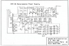
I've noticed there are at least 2 partially different amplifiers called the "STA-35 Renaissance", built by Woodside after Radford went bust (or sold the design?).
One model has ECC88 and the other has ECC81 and some other differences. I've also seen some having a toroidal power transormer.
The date on the bulletin of the ECC88 model seems to be '89 and the schematics of the ECC81 model are from '91.
Does anyone have any info on why the changes have been made?
Attachments
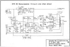
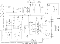
I noticed that schematics of the phase inverter, V2 has un-balanced gain of the two phases.
The plate resistors are both equal at 15k, but the common cathode resistor is only 2.2k, that is Not a CCS. That stage has some 2nd harmonic distortion.
The un-balanced gain is inside of the global negative feedback loop, so it will reduce most of that 2nd harmonic, perhaps there is some residual 2nd harmonic distortion there, to give a warm sound to the amplifier.
Last edited:
One section is a pentode the other a triode , maybe with those components is "balanced" who knows ...
Dopanatoru,
I doubt the phase splitter output voltages are matched.
Here is why:
The pentode grid g1 is driven. That changes its cathode current.
The pentode's change in cathode current is divided into two paths: the common cathode resistor R15 2.2k, and the triode's cathode.
The pentode's cathode current change and the pentode's plate current change are almost equal (the screen current changes too *).
* The pentode's screen is at a constant 200V, so as the pentodes grid g1 changes, the screen current changes too.
But now, there is less current change into the triode's cathode because the common cathode resistor sucks some of it up.
But the triode's cathode current change and triode's plate current change are equal, so the triode's change in plate current is less.
So, more current change into the pentode's 15k plate load; and less current change into the triode's 15k plate load.
More current change in 15k = more voltage change in 15k. Pentode
Less current change in 15k = less voltage change in 15k. Triode.
Un-balanced phase inverter outputs.
It is all about current steering to one 15k versus current steering to the other 15k resistor.
If it was me, I would not count on the pentode's change of screen current to make up for the difference of the pentode's plate signal voltage, and the triode's plate signal voltage.
Just my analysis of the circuit.
Last edited:
I don't say that the circuit is well balanced or not ... until somebody will measure it
The ideea is simple , with 2 identical triodes the circuit is unbalanced with equal plate resistors because one triode is grid driven , the other cathode driven , the gain is different . Only a cathode current source will force the circuit to be balanced , or if you use unequal plate resistors as they did in many designs
Now , our circuit has equal plate resistors but is using a triode and a pentode ... the result can be even more unbalance or the opposite , if the designer was very clever . You can't tell without a simulation , calculation or practical test .
Last edited:
Consider A1 operation (no g1 grid current in the pentode, no g1 grid current in the triode).
g1 grid current in either phase inverter tube would be a major problem.
I am talking about signal current, not quiescent current for all the tube elements.
My point is that for equal plate loads, and coupled cathodes:
Equal plate amplitudes if the cathodes are connected to a CCS (constant current sink).
OK.
Un-Equal plate amplitudes if the cathodes are connected to a resistance.
Electrons can only steer to these four places in that circuit: cathode 1, cathode 2, cathode Resistor, screen.
The plates get All of that current, Except the current in the cathode resistor and the current in the screen.
No electrons are lost (I hope, or we have a bucket of Protons, and that is not friendly).
Who wants to run a simulation of that phase inverter?
Who wants to build and measure that phase inverter?
Feel free to do so.
Clever is very nice.
But what pentode tube designer can give you the exact ratio of changing plate current to changing screen current as the pentode's g1 voltage is varied and as the pentode cathode's voltage is varied when it drives 2.2k in parallel with the triode's cathode)?
I am nothing other than a skeptic on this one.
For the phase inverter in question, I am putting my money on one of these:
The designer did not notice the un-equal plate amplitudes.
The designer intended to have un-equal plate amplitudes (inside of the global negative feedback loop).
Last edited:

The screen of the pentode is not relevant , with 2 different triodes in theory you can achieve balance using equal plate resistors .
It is all related on how much gain has the triode grid driven vs the cathode driven . If the cathode driven triode is a type with higher transconductance ( and with the right amount ) then the circuit will be balanced .
It is all related on how much gain has the triode grid driven vs the cathode driven . If the cathode driven triode is a type with higher transconductance ( and with the right amount ) then the circuit will be balanced .
there is a nice explanation as to the Radford design using a pentode triode tube long tail pair....
https://www.diyaudio.com/community/threads/long-tail-pair-phase-inverter-with-pentode.73463/
https://www.diyaudio.com/community/threads/radford-pentode-triode-ltp-splitter.140028/
valve museum....Radford 35, this is where it all started ... http://www.r-type.org/articles/art-097.htm
https://www.diyaudio.com/community/threads/long-tail-pair-phase-inverter-with-pentode.73463/
https://www.diyaudio.com/community/threads/radford-pentode-triode-ltp-splitter.140028/
valve museum....Radford 35, this is where it all started ... http://www.r-type.org/articles/art-097.htm
Depanitoru,
In reference to your Post # 7:
Let us analyze a two triode phase inverter, with the cathodes tied together, equal plate load resistors;
And:
Either a common cathode resistor (*);
Or a common CCS (**) to the cathodes, (CCS = an extremely high impedance constant current sink).
Start with the rule, that the signal levels are within the linear range of the phase inverter, and so Zero grid current is drawn from either triode.
Let's not include the high frequency effect of miller capacitance, so we are discussing low and mid frequencies.
First, (*) a single resistor for the two cathodes. When signal drives g1 (the driven triode), and g1 of the other triode goes to signal ground),
Then where does the driven cathode signal current go?
Some goes to the other triode's cathode.
But some goes to the single resistor of the two cathodes.
That means not all of the driven triodes cathode current (which is also its plate current).
It looks like the common cathode resistor is "robbing" some of the driven triode's cathode current from going to the other triode's cathode.
As a result, the plate current of the other triode is less; so it has less plate signal swing.
The only way to fix this (if you keep the common cathode resistor), is to increase the plate load resistor of the other (un-driven) triode.
Second, (**) a CCS for the two cathodes. When signal drives g1 (the driven triode), and g1 of the other triode goes to signal ground),
Then where does the driven cathode signal current go?
Effectively, no signal current goes to the CCS. (Super high impedance, right?)
All the current goes to the other triode's cathode; so all the signal current goes to the other triode's plate, right?
There is No need to fix this circuit, because its superior amplitude balance is as good or better than the output stages tubes' and output transformer's balance is.
I have built lots of phase splitters using CCS (NPN, LM317, and LM334). With matched plate load resistors, and a pair of matched 10Meg Ohm 10X probes, the balance is extremely good.
Build your own, if you doubt the results, and prove it for yourself.
A real circuit is better than a simulated circuit (you can not enjoy listening to a simulation).
Just Sayin'
I will say it differently, but say it one more time . . . equal signal current, in equal load resistors, has equal gain (of course of opposite phase).
I hope that explains the principle, both for newbies, and for those of us who forgot what we already knew.
I know, global negative feedback fixes a multitude of 'sins' (distortions, frequency response, damping, etc.) that are inside the negative feedback loop.
Just one approach to design. There are other approaches.
Last edited:
i would rather keep it simple, but this Radford is too elegant to simply ignore....The screen of the pentode is not relevant , with 2 different triodes in theory you can achieve balance using equal plate resistors .
It is all related on how much gain has the triode grid driven vs the cathode driven . If the cathode driven triode is a type with higher transconductance ( and with the right amount ) then the circuit will be balanced .
i would like to find out if it keeps its promises, of course the quality of the irons and the stiffness of the psu counts big too...
i am building it too. pentode provide a lot of gain since this pentode will cathode couple the signal to the cathode of the triode section, it makes sense that this pentode have lots of gains and low cathode output impedance too...
plate load resistors and cathode currents determine gains, but the plate voltages determine output swings...
i think the beauty of this is the non use of sand in the implementations...
my limited experience with sand is that reliability is not that high, for the measly gains achieved, i would rather go all out tubes in the amplification department..
Attachments
Last edited:
yes, but does not guarantee equal plate voltages, and so unequal plate voltages produce unequal output swingsI will say it differently, but say it one more time . . . equal signal current, in equal load resistors, has equal gain (of course of opposite phase).
the plate load resistors determine the voltage gain, but the plate voltages determines ac output swings....
If you have a dual triode (not of the mixed triodes, like a 12AX7 and 12AU7 in the same envelope), and you use Either a very high resistance cathode resistor going to -150V, or use a real CCS, and if the plate loads are equal, not only the signal amplitudes will be equal, the plate voltages will be quite close together. If not, purchase a properly manufactured and match tested tube.
I have never seen such a circuit like that has a large difference in DC plate voltage, that gets in the way of the signal voltage swing.
That indicates either a badly balanced dual triode, or indicates that the design is cutting it too close.
The most direct solution is often the easiest one, and often gives the best results.
If there is not enough output swing from a dual triode LTP or CCS phase splitter, then design it with different quiescent conditions, such as more negative bias voltage, more B+, higher plate load resistance, etc. You will get more signal swing from the plates.
If that does not work, then find another tube type number of a dual triode that is more suited for the task at hand.
Question:
Would you use two badly matched carburetors for your Datsun 240Z?
Just my opinions and my experience
Isn't this a case of well tuned carburetors, different needles (or jets)?Would you use two badly matched carburetors for your Datsun 240Z?
Old Hector,
Some dual triode tube manufacturers have had bad tolerance control (that is an art and a science).
Suppose Datsun hired a contractor that had bad tolerance control when they made carburetors?
Tweaking adjustments and new needles might not fix that.
At least we can get to many things on a carburetor, but you can not fix a dual triode (do you have a vacuum pump, RF heater, glass working facility, etc.?).
- Home
- Amplifiers
- Tubes / Valves
- Radford STA-35 different versions