Hi Miles,
And in the case of the Radford flagship, STA100, they probably also though about getting rid of all those many EF184/6EJ7 on stock 😉
(For those who don´t know the circuit: It employs two EF184 pentodes in its Radford "signature type" Schmitt inverter)
Regards,
Tom Schlangen
Why these folks persist in doing stuff like this escapes me completely [....]Somebody's got too much time on their hands.
And in the case of the Radford flagship, STA100, they probably also though about getting rid of all those many EF184/6EJ7 on stock 😉
(For those who don´t know the circuit: It employs two EF184 pentodes in its Radford "signature type" Schmitt inverter)
Regards,
Tom Schlangen
STA100:
http://www.freeinfosociety.com/electronics/schemview.php?id=2364
Two pentodes for the splitter, with the screens bypassed to the cathodes (no local UL effect). So no attempt at local linearization.
It's built like a high gain SS amp. with global feedback. This is definately not a splitter I would use. Connecting some feedbacks from the output stage to the splitter screens might improve it.
Don
smoking-amp said:STA100:
http://www.freeinfosociety.com/electronics/schemview.php?id=2364
Two pentodes for the splitter, with the screens bypassed to the cathodes (no local UL effect). So no attempt at local linearization.
Don
Yup, this one is flighty.I also didn't get on with this LTP design and found it produced high thd and this amp uses alot of global nfb to reduce it. It could benefit from a CCS in the tail but doubt it is worth it. So it is easily possible to get an 100W amp with only 3 stages but the sound quality is questionable; the power supply needs reworking. Some decades ago I did have the amp and modified it to a 4 stage amp reconfig the EF184's as triodes and more front end gain. That really sweetened it up.
Those of us who used this amp on stage in the early 1970's often commented when it went wrong it certainly fired up. Those KT88's were wrung to the limit for shortest life.
richy
Somebody's got too much time on their hands.
And somebody got out of bed the wrong side 😀
It's known as an inquiring mind. Ho-hum, wouldn't this hobby be dull if only two types of phase splitter were allowed?
"wouldn't this hobby be dull if only two types of phase splitter were allowed?"
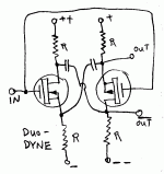
I think I saw something like this posted before on a screen drive thread, maybe with some zeners in the sources to equalize the power supplies. Maybe was Ken? Could call it the Duodyne or Compledyne, or depending on ones mood, the Azodyne splitter. 😀
Nicely symmetrical. Could use matched Beta NPN and PNP too, I suppose.
Don
Attachments
Merry -Go- Round Splitter
This one's got me excited. Looks like the "Old Guys" missed a big one.
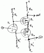
This takes it's inspiration from the See-Saw splitter, but goes the whole 9 yards (instead of half way). Two unity-gain inverters are connected in a 360 degree loop, like an oscillator. Then the gain is adjusted to just below unity by a pot. (Unity gain pot.) The closer the loop gain is to unity, the higher the sensitivity (or gain) to tilting the loop, with the signal input put in on one screen grid.
So stage gain (input to output) can be adjusted arbitrarily high, but gets risky up there (oscillates). The input on a screen grid is quite convenient for direct coupling from a previous gain stage.
Don
edit:
May be able to improve the linearity further by connecting the unused screen grid (V2 side) to a resistive divider between V1 plate and a +Vscrn reference voltage. Adjust the divide ratio so the screen signal matches (inverted) the input on the other screen.
Maybe have to put a Mosfet follower off the V1 plate to avoid any current drawn by the divider. Or, just tweek the value of Rl up a little (for V1) to compensate for the divider resistance in parallel with it.
Attachments
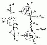
One could also configure the Merry-Go-Round splitter to use the G2's for the unity gain feed-around loop (only needs to achieve just under unity loop gain, no problem), and feed the input in on the high Z G1 (V1 side). Horses for courses. Whichever fits best.
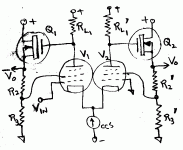
This Merry-Go-Round scheme (dual sub unity gain inverters in a loop) can make a nice center tapped inductor, plate load equivalent, if its implemented with P-chan Mosfets up top. (Drain to gate resistive divider feedbacks, or feedarounds) The P drains just become the loads for the diffl. tubes below (no load resistors). There's no inherent Mu factor with the Mosfets, so they will need source resistors to linearize them, but that just helps reduce the gain down to unity anyway.
And it could even be used as a stand alone splitter up there too, for that matter. A very useful circuit.
And it could even be used as a stand alone splitter up there too, for that matter. A very useful circuit.
At the risk of waking this thread from its happy slumbers after nearly 6 years, whilst researching things Radford as I really need to start planning the rebuild of my STA-25 I cam across some interesting empirical information. ECF82s in Radford STA15 amp
For the non-clickers, it would seem that the 2 halves of the ECF82 are not that well Matched (unsuprisingly) which leads to the phase splitter being a major source of THD. That could at least explain why the MA100 had dual pentodes for the phase splitter.
If It's just DC imbalance shouldn't be too hard to adjust for?
The STA Renaissance series just uses a pot (2.2k) to feed the two halves of the ECF82/6U8, with the B+ tied to the center pin.
- Status
- Not open for further replies.
- Home
- Amplifiers
- Tubes / Valves
- Radford pentode-triode LTP splitter


