I suggest to disconnect the feedback loop just for the notes of Kay.
If without FB it stay quite, is it possible to check the voltages on some point of the circuit and, in case, take some lab mesaurement
Walter
If without FB it stay quite, is it possible to check the voltages on some point of the circuit and, in case, take some lab mesaurement
Walter
Ciao Walter, I will try and disconnect the NFB loop as you suggest, take V measurements and check the output on oscilloscope.
Keeping in mind though, that these amps are from app. 1990, and has functioned with no problems for about 26 years. So the basic design should be allright - if all components are doing their job.
Keeping in mind though, that these amps are from app. 1990, and has functioned with no problems for about 26 years. So the basic design should be allright - if all components are doing their job.
What was the load to the amp when this happened? Did you leave the speaker terminals open? Note that almost any tube amp needs to be loaded when powered up.
I'd also replace the grid stoppers by resistors of at least ten times the value.
In fact there are ratings for the maximum grid to cathode resistance for the EL 34. Philips datsheets say 700 kOhms for autobias and 500 kOhms for fixed bias. So, these 220 kOhms are well in the ballpark.
Best regards!
Hallo, I don't think I had a load connected at that point, but there was for sure no signal applied. Isn't the load only critical with an input signal?
I have changed the Cathode resistors from 470K to 220K as advised, but will leave the Grid resistors at 220R for the time being. As I wrote in above post, the amps have worked for decades with no issues.
It will be a few weeks before I have time to work on them again, but will update the thread with results..
jvhb,
Did you mean change the Grid Resistors from 470k to 220k?
If you do that, you should change the coupling caps at the following ratio:
470/220 = ~ 2 times the capacitance. That will make the low frequency pole the same as the original when you use negative feedback.
Did you mean change the Grid Resistors from 470k to 220k?
If you do that, you should change the coupling caps at the following ratio:
470/220 = ~ 2 times the capacitance. That will make the low frequency pole the same as the original when you use negative feedback.
Second on reducing R18 and R19. There are two EL34 per grid leak R so the value should be half. As is, it is like 1M on one EL34 (out of spec)
jvhb,
Did you mean change the Grid Resistors from 470k to 220k?
If you do that, you should change the coupling caps at the following ratio:
470/220 = ~ 2 times the capacitance. That will make the low frequency pole the same as the original when you use negative feedback.
Yes sorry, I meant the Grid to ground resistors (R18/R19) have been changed to 220K, while the Grid stoppers are left at 220R.
Will check the Frequency response/roll-off at the low end, but I think the LF pole is still plenty low. I measured it last week, but can't find those notes now.. Thanks for your help.
Done..
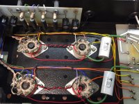
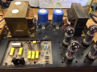
Hi, I am now done with both amps, and they are working perfectly.
I have attached some pictures.
All the critical caps and resistors have been replaced, as well as all the EL34 tube sockets for good measure.
Both measure very close, with Bias of 44-46mA per tube (about 18w each).
Max output is 50W@0,3% THD into 8 ohm load. Distortion residual looks quite nice, a bit of H2/H3 mix.
Frequency response is 0dB from 20hz to 10Khz. -1db at about 50Khz.
Voltages @ 230VAC:
B+ 450V
Plate voltage (Anode to Cathode): 413V
Cathode resistors (680R): 33V
I tried disconnecting the NFB as suggested, and noted the following:
- Output still stable and clean, but with higher distortion (as expected).
- Gain increased to about 450x instead of 31x. This surprised me a bit. Is that normal?
They have both been running for over 24 hours with no issues, and sound very good.
Only thing that bothers me, is that none of the components I have replaced were actually defective - at least not that I could measure.
Would have been nice to find "the smoking gun" after all..
Thanks to all for your help.
Attachments
gain 450 / gain 31 = 14.5:1
14.5:1 = 23dB negative feedback, within range of quite typical feedback for that era.
You are still wondering what made the circuit blow up, how about the fact that each pair of 2 EL34 tubes in parallel had a grid leak resistor of 470k Ohms (equivalent to 940k Ohms per tube).
What if the tubes started running the grid voltage slightly positive?
Then more current and hotter, more grid voltage, more current and hotter, more grid voltage, Bang!
Perhaps there was more current than you thought in one or more of the cathodes, if one of the electrolytics was leaky.
The voltage could still be 33V, but at more current. The tube gets hotter, draws more current, gets hotter, draws more current, . . .
And how about the possibility that one of the coupling caps went leaky, but only under rising ambient heat and driver plate voltage (not able to be seen under ohmmeter voltage, and normal room temperature).
It is hard to tell which part went first, you likely will never know.
Hopefully, you have made enough changes so that it never happens again.
Last edited:
53 db without global feedback seem typical....
if that were mine, i will decrease feedback to a point that distortions are smaller...
change the 2.2k to 4.7k ohm feedback resistor, to the output, i will add a 10 ohm 2 watt resistor in series with a 0.01ufd/400 volt cap...
you have enough gain to play around with...
if that were mine, i will decrease feedback to a point that distortions are smaller...
change the 2.2k to 4.7k ohm feedback resistor, to the output, i will add a 10 ohm 2 watt resistor in series with a 0.01ufd/400 volt cap...
you have enough gain to play around with...
Thanks guys. I will leave well enough alone for now, and put them "to work" for a while, before doing any other modifications to the circuit.
- Status
- Not open for further replies.
- Home
- Amplifiers
- Tubes / Valves
- Radford MA50 problems and questions