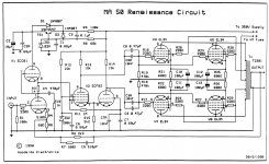
Hi, I am having some problems with a set of Radford RA-50 Renaissance mono amps, and I could use some help. Schematic is attached.
They have now twice gone faulty with the same symptoms:
C11 (Cathode to ground cap) exploded (literally), and fuse blown. The corresponding V4 tube actually survived this last time, but died the first time it happened.
All tubes were replaced with a matched set of JJ EL34 about 10 running hours ago. The four caps in question (C10 to C13) were replaced at the same time, using Panasonic 100uF/100v.
I can't find the reason this keeps happening. Before the first fault, the amps had been used for about 20 years without any exploding caps. So what has changed? Are the new current production JJ EL34 just not strong/stable enough for this design?
I have checked voltages and Bias several times, and they all seem to be in order - as far as I understand (and I am not a expert on Vacuum Tube amplifiers).
Readings taken in idle with an 8ohm dummy load:
B+ is 460V
Plate to Cathode is 400V (when warm).
Screen (G2) voltage is 408V (to Cathode). The Screens are drawing about 6-8mA each.
All tubes are fairly evenly biased around 49-51mA. So about 20W on each.
This being a Cathode Biased design, that should be a good value afaik.
Grid to Screen is app. 32V.
Voltage across Cathode resistors are app. 32V.
Notes to the Schematic:
There are some difference between the sch. and the amps in question: The output tube/Power section is correct, as well as Resistor and capacitor values. But the driver/phase inverter section has two trimpots not shown on the schematic: There is a 2K trimmer between R12 and the plates of ECF82 (R13 and R14). I assume this is to balance the two halves of the power/output.
Then there is a 100R trimmer, which I haven't quite worked out yet. But it is connected from the mains transformer and seems to be paralled across V2, the ECF82. Will try and draw out the precise connections later..
To sum up:
- What can be the cause of the faults and exploding caps?
- Is there perhaps some flaws in the circuit I could/should remedy?
Thanks!
Attachments
Curious fault.
Assuming it really is only V4 that is affected, then points to only a few things.
R22 could be intermittent open circuit, or the soldering to it could be dry or the Track to it is cracked somehow.
The valve base could be faulty with tracking somewhere in it.
C3/C3A could have an intermittent short or resistive short.
If in doubt replace the valve socket, R22 and C3.
Really cannot see the point of C3A (and C8A) so leave them out.
Hello Gentlemen, thanks for your suggestions.
The "C3" caps are actually called C9 and C9A, the top of the "9" is just a bit faded on the schm. C8A and C9A are 10nF Styro caps.
I have measured all the resistors and caps you mention, as well as all the other resistors, several times, so I am certain they all have correct values.
However intermittent shorts, perhaps occuring only above a certain temperature is a possibility I can't rule out.
I can replace all the critical resistors and caps, to just rule these out as fault source, but didn't want to do that until at least understanding the circuit a bit better.
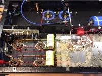
I have attached some pictures showing the underbelly of the beast 🙂
Yes curious fault indeed, as both amps have the same problem.
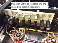
On this one (lets call it amp#1) it was both times V4 and the corresponding Cathode capacitor (C11 on the schematic, but labelled C8 on the PCB in the actual amp) that went bang.
On amp#2 it was also V4 the first time. Then I replaced the dead cap (C11), and powered it up slowly on variac to about 200VAC, and after 5 min, the V6 tube started sparking inside, and its Cathode cap (C13) promptly exploded right in front of me! 😱
So it not only V4, but all the exploding caps (and sparking tubes) have been on the same side of the output tube stages - the bottom half seen on the schematic.
I don't if this is just a coincidence, or a clue to the root cause of the problems. It is a bit suspicious isn't it?..
The "C3" caps are actually called C9 and C9A, the top of the "9" is just a bit faded on the schm. C8A and C9A are 10nF Styro caps.
I have measured all the resistors and caps you mention, as well as all the other resistors, several times, so I am certain they all have correct values.
However intermittent shorts, perhaps occuring only above a certain temperature is a possibility I can't rule out.
I can replace all the critical resistors and caps, to just rule these out as fault source, but didn't want to do that until at least understanding the circuit a bit better.
I have attached some pictures showing the underbelly of the beast 🙂
Yes curious fault indeed, as both amps have the same problem.
On this one (lets call it amp#1) it was both times V4 and the corresponding Cathode capacitor (C11 on the schematic, but labelled C8 on the PCB in the actual amp) that went bang.
On amp#2 it was also V4 the first time. Then I replaced the dead cap (C11), and powered it up slowly on variac to about 200VAC, and after 5 min, the V6 tube started sparking inside, and its Cathode cap (C13) promptly exploded right in front of me! 😱
So it not only V4, but all the exploding caps (and sparking tubes) have been on the same side of the output tube stages - the bottom half seen on the schematic.
I don't if this is just a coincidence, or a clue to the root cause of the problems. It is a bit suspicious isn't it?..
Attachments
Another tack, in North America, we have an ongoing problem with all of JJ's Octal production. 😡 Floor sweepings is a fair rating of their quality. Here is an example of JJ grief. The JJ tubes sold in Europe may be of better quality. Still, it may be worth while to try New Sensor's Saratov, Russia, made tubes. EH "fat bottle" 6CA7s are not very costly and are (IMO) a good way to rule tube failure out.
Buy tubes from a reliable dealer who is known to match sets well and culls "infant mortals" out.
Buy tubes from a reliable dealer who is known to match sets well and culls "infant mortals" out.
...all the exploding caps (and sparking tubes) have been on the same side...
So replace that grid cap.
The cathode caps can't explode unless there is HUGE current in the tube. Bad tubes are a possibility. However "all on one side" points to some common fault. Grid cap and resistor are the common point. The timing suggests cap aging. However it is *possible* that a poor solder joint on the resistor held-on for 20 years before tarnish made it goofy.
Huggygood>>
About measuring the OPT primary, do you mean a procedure like this:
Measuring Primary Impedance
- I have not done that no, but I can do it tomorrow...
Yes same model of speaker, Snell EIII. Although the last fault (with C13 on amp#2) happended on the workbench, and not with speaker connected.
PRR>>
Thanks for your reply. Yes replace grid cap, I can do that.
But isn't it unlikely that the same cap, either C9 or C9a, is per chance intermittently bad on both amps? I mean, 1000V MKT or Styrol caps don't usually tend to fail with age, do they?
I resoldered all the Cathode resistors (one for each tube) when I last replaced the "exploding" caps and the tubes, so pretty sure that those solder joints are good. But will replace those resistors before fitting new tubes again. Just to be sure..
But the circuit/topology as such, looks alright to you?
Thanks, I appreciate your help guys.
I suggest to reduce the R18/R19 to less then 250k, this to reduce the grid current avalance.
This stabilizes the power stage better with no side-effects.
Also a 100ohm cc or wirewond 1/4w resistor in series with the anodes, mounted as close to
the tubesocket as possible. ( i hope the R20 etc , screen stoppers are close to the tube
sockets, and so the R16 etc)
The JJ EL34 should not have any problems here.
Hej petertub,
Thanks for your suggestions, I will have a look at that
Yes the Grid resistors are right on the sockets.
But the Screen stoppers (R20 etc) are actually not close to the sockets, the are mounted on a PCB on the topside of the amp, with app. 20cm leads going down to the tube sockets. Would it be a big improvement (to stability) to move them down?
- Can anyone confim that 50mA (20W) Bias is suitable for this design and EL34 (25W) tubes?
Last edited:
Yes, it's ok....and anyone confim that 50mA Bias is suitable for this design and EL34 (25W) tubes?
The fixed cathode resistors decides this, measure them to be on the safe side.
( and change the grid resistors to a smaller value while you are working )
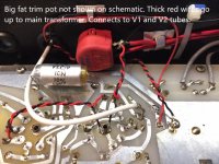
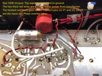
Trimmer across Tube filaments
Hi, so while I am waiting for new parts to arrive, I had a second look at that big red 100R trimpot, that wasn't shown on the schematic:
It is connected across the Filaments of V1 and V2 (ECC81 and ECF82), with the Wiper going to ground. See attached picture.
I don't understand the purpose of this trimmer. How should it be adjusted?
Attachments
Check your voltage readings again. Something is either changing radically during your measurements, or some of the readings were wrong.
Quote:
B+ is 460V
Plate to Cathode is 400V (when warm).
Answer: That says that there is 60V total drop in two parts: the 680 Ohm cathode resistors, and the DCR of the 1/2 winding (plate connection) of the output transformer.
Quote:
Screen (G2) voltage is 408V (to Cathode). The Screens are drawing about 6-8mA each.
Answer: 460V at the center tap of the output transformer but only only 408V at the screen (8mA x 220 Ohms = 1.76V). But that means there is 408V + 1.76V = 409.76V at the transformer screen tap (40% of the 1/2 winding).
But 460V - 409.76V = 50.24V drop in only 40% of the 1/2 winding of the output transformer. There will not be 50V drop through that wire unless the tube is drawing lots of current (plate plus screen current).
The 50V drop is surely when the amp is not in normal operation, but is in its broken state.
Quote:
All tubes are fairly evenly biased around 49-51mA. So about 20W on each.
This being a Cathode Biased design, that should be a good value afaik.
Grid to Screen is app. 32V.
Voltage across Cathode resistors are app. 32V.
Answer: 49mA x 680 Ohms = 33.3V
51mA x 680 Ohms = 34.68V
51mA x 400Vp-k = 20.4W
This is surely when the amp is at normal operation.
But with 50V drop in 40% of the 1/2 winding, and 34V drop in 680 Ohms, then that would mean the DCR of that wire would be: X Ohms/50V = 680 Ohms/32V,
X = (50V x 680 Ohms)/32V = 1063 Ohms (not likely).
More: (that has already been stated by or hinted at by others)
1. All of the coupling caps should be rated at 600V or more.
Of course you probably will not notice the difference if you remove the two 10nF caps.
2. Any bad parts that open or cause a bad connection might cause excess current:
Control Grid Grid Stopper resistor (floating grid is very bad).
Control Grid Grid Leak resistor to ground (floating grid is very bad).
Tube Socket connections to the tube, and to the wiring.
Suppressor Grid connection (floating does or does not cause excess current, I do not know).
3. There is no rating for the Pentode EL34 maximum control grid resistor to ground.
The Pentode 6CA7 is regularly substituted for the EL34 (and the other way around too, they have similar ratings). The 6CA7 rating for maximum control grid resistor to ground is 700k Ohms.
You have 2 tubes in parallel, 700k Ohms/2 = 350k Ohms max.
I agree with petertub, use a lower resistance control grid resistor, no more than 330k Ohms, but 270k Ohms or 220k Ohms would be better.
Quote:
B+ is 460V
Plate to Cathode is 400V (when warm).
Answer: That says that there is 60V total drop in two parts: the 680 Ohm cathode resistors, and the DCR of the 1/2 winding (plate connection) of the output transformer.
Quote:
Screen (G2) voltage is 408V (to Cathode). The Screens are drawing about 6-8mA each.
Answer: 460V at the center tap of the output transformer but only only 408V at the screen (8mA x 220 Ohms = 1.76V). But that means there is 408V + 1.76V = 409.76V at the transformer screen tap (40% of the 1/2 winding).
But 460V - 409.76V = 50.24V drop in only 40% of the 1/2 winding of the output transformer. There will not be 50V drop through that wire unless the tube is drawing lots of current (plate plus screen current).
The 50V drop is surely when the amp is not in normal operation, but is in its broken state.
Quote:
All tubes are fairly evenly biased around 49-51mA. So about 20W on each.
This being a Cathode Biased design, that should be a good value afaik.
Grid to Screen is app. 32V.
Voltage across Cathode resistors are app. 32V.
Answer: 49mA x 680 Ohms = 33.3V
51mA x 680 Ohms = 34.68V
51mA x 400Vp-k = 20.4W
This is surely when the amp is at normal operation.
But with 50V drop in 40% of the 1/2 winding, and 34V drop in 680 Ohms, then that would mean the DCR of that wire would be: X Ohms/50V = 680 Ohms/32V,
X = (50V x 680 Ohms)/32V = 1063 Ohms (not likely).
More: (that has already been stated by or hinted at by others)
1. All of the coupling caps should be rated at 600V or more.
Of course you probably will not notice the difference if you remove the two 10nF caps.
2. Any bad parts that open or cause a bad connection might cause excess current:
Control Grid Grid Stopper resistor (floating grid is very bad).
Control Grid Grid Leak resistor to ground (floating grid is very bad).
Tube Socket connections to the tube, and to the wiring.
Suppressor Grid connection (floating does or does not cause excess current, I do not know).
3. There is no rating for the Pentode EL34 maximum control grid resistor to ground.
The Pentode 6CA7 is regularly substituted for the EL34 (and the other way around too, they have similar ratings). The 6CA7 rating for maximum control grid resistor to ground is 700k Ohms.
You have 2 tubes in parallel, 700k Ohms/2 = 350k Ohms max.
I agree with petertub, use a lower resistance control grid resistor, no more than 330k Ohms, but 270k Ohms or 220k Ohms would be better.
Last edited:
Please disconnect the feedback loop and test the amp if the issue still exist
Do you have a scope?
Walter
Do you have a scope?
Walter
Last edited:
Thanks for all your suggestions. I am in the process of changing all the critical resistors and caps as mentioned, and will also reduce the Grid to ground resistors, from 470K to 220K.
The original coupling caps were 1000V MKP with 630V rated Styrol in parallel. I will replace them with a single 1600V Vishay MKP.
Regarding the B+ of 460V, I think this reading may have been taken before the tubes were warmed up and drawing power, that is why the numbers don't add up. Sorry about that. I will recheck voltages and check the math, once the amps are together and running again.
A "Humdinger"! - yes that makes sense, just didn't know about it. Have found a good explanation here:
The Valve Wizard
Have a nice audio day 🙂
The article you posted "The Valve Wizard" mentions the AC current in the filament as causing a magnetic field, and the problems caused by that.
Some tubes have a multiple path of vertical up & down filament wire in the cathode.
That potentially has the problem. The magnetic field goes "outward" through the cathode.
But there are some tubes that instead us a very fine spiral filament that goes up once, and down once in the cathode. That causes the magnetic field to go up and down in the cathode, it does not go out through the cathode. That magnetic field is less of a hum problem when this is implemented properly, than the non spiral filament tubes.
Hi, an update: After replacing all the relevant/critical Caps and resistors, as well as the Octal sockets, Amp#1 has been running for a few days now, with no issues. It is quite a good amplifier actually, with THD around 0.01% at 10W output, and 50W max output before clipping. Draws app. 130W from mains.
What bothers me though, is that I haven't found the root cause of the repeated failures: All the components I have replaced measures perfectly good, so I still don't know what the defect was (is?) :/
What bothers me though, is that I haven't found the root cause of the repeated failures: All the components I have replaced measures perfectly good, so I still don't know what the defect was (is?) :/
...Although the last fault (with C13 on amp#2) happended on the workbench, and not with speaker connected.
What was the load to the amp when this happened? Did you leave the speaker terminals open? Note that almost any tube amp needs to be loaded when powered up.
I'd also replace the grid stoppers by resistors of at least ten times the value.
In fact there are ratings for the maximum grid to cathode resistance for the EL 34. Philips datsheets say 700 kOhms for autobias and 500 kOhms for fixed bias. So, these 220 kOhms are well in the ballpark.
Best regards!
- Status
- Not open for further replies.
- Home
- Amplifiers
- Tubes / Valves
- Radford MA50 problems and questions