Service manual here
https://www.vintageshifi.com/repertoire-pdf/pdf/telecharge.php?pdf=Rotel-RA-930AX-Service-Manual.pdf
Hello, I am repairing a rotel ra930ax amp. The core issue was the left channel not working.
When I acquired the amp, one of the rectification fuses F902 was blown, which was easily replaced. Someone had also bodged a 10A (!) fuse for the left channel, which I also promptly swapped out.
The left channel still didn't work. I then spotted a pcb scratch, which i bridged, and now the left channel worked. However, there was a distortion compared to Right.
None of the transistors seem obviously faulty. I checked voltages, and I find that there are some differences in the left vs right.
Key issue is that the base of q615 is +8.5volts (EXPECTED = +1.2v). The base of q 613 is +7V. (whereas it should be c -0.5v as per schematic). Oddly enough, when I disconnect the speaker, this +7 drops to +1.6 (still the wrong voltage).
The right side doesn’t have this issue, using exactly the same speaker and cables. Voltage at q614 stays stable irrespective of speaker presence.
I checked for other circuit scratches/ breaks and I cannot find any.
Bit stumped, any pointers would be greatly appreciated.
You need to check that both 0.22 ohm resistors are OK as they would most likely get taken out with a fault condition.
8.5 volts on the base of Q615 means you should be seeing around 7 to 7.5 volts at the speaker output terminal which is wrong of course. The speaker should have protested loudly and so I'm guessing that didn't happen.
Start with the basics. Check the 0.22 ohm's and check the DC offset with no load attached. I would also recommend you use a DBT (dim bulb tester) to prevent any disasters.
Thanks mooly
Yes I am using a DBT (should've mentioned)
The speaker voltages are 90mv (right) and 92mv (left)
The 0.22 ohms all measure c 0.5ohm in circuit.
the Bias voltage on the right is 3.2mV but the bias voltage on left measures 0, at any position of the biasing variable resistor. This does look suspicious.
I desoldered R629 (one of the .22ohm which is across the test points for L channel, but it does measure 0.3 ohms on the meter.
Also the variable resistor does seem to change resistance (measured it) when turned so it doesnt seem shorted
Connecting the speakers changes the voltage .. think this is an important clue, not sure though what to do with it. I checked the resistor across the fuse but that is fine too 33.3kOhm.
onnecting the speakers changes the voltage .. think this is an important clue,
That is very strange,
The readings you have posted all sound OK and I'm assuming those were with no load attached.
I think you are going to have to look at the voltages with a load attached next. If you are using a DBT and you see 8.5v on the base of Q615 then that voltage should carry through to the output terminal (less around 1.5v of the combined base/emitter volt drops of Q615 and Q619). That voltage would (should) cause a large current to flow in the speaker and cause the lamp to light.
Is that happening?
That voltage would (should) cause a large current to flow in the speaker and cause the lamp to light.
No, the lamp is off during operation, and to my ears now, i dont hear any perceptible distortion on the L channel. The voltages are still 'wrong' as above.
I will report back this evening with a summary of voltages with and without speakers attached.
That doesn't sound right then.No, the lamp is off during operation,
If you have 8.5 volts on Q615 base then that voltage should also be across the speaker (check that it is) and that should draw an amp or so of current through the speaker voice coil (8 volts across 8 ohms is 1 amp) and that should really be lighting the bulb.
So here is a summary of where we are.
Sounds:
The amp is working. Right sounds very good. Left sounds just as good too... I cannot detect appreciable distortion, though I have a slight nagging feeling higher frequencies are slightly lost. But this could be psychological.
Voltages:
Left and right speaker + to gnd are about 80mv
Bias voltages
L : c 3mV
R: c 5mV
Rail voltages
+36V and -36.5V (not on DBT)
the regulated + - 18V are also present.
The base of Q619 is c 7V. Whereas it is -1.2V on the Q620
Base of Q617 is c 8.2V, base of Q618 is c-1V
IF it matters, I am measuring with the -Ve probe of DMM clipped to the chassis. +Ve on to the measuring points.
Its driving me nuts as to what might be wrong, if at all -- the sound is fairly normal. I would have expected a much worse outcome with those measured voltages.
What am I missing?
DC values at the output (Q615, Q617 and Q619, Q621) will depend on values around Q613, assuming the output stage transistors are not damaged.
The DC values around Q613 depend on everything to the left of Q613.
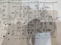
Measure the voltages as listed on the circuit diagram (red) and let us know what the readings are. Provide the readings as shown (in blue)... as well.
Once the DC stability is established, trace the audio signal from its input, towards the output and ensure everything looks okay. You'll need a signal generator and oscilloscope. This will highlight any slightly damaged semiconductor(s)... easier and more reliable, than removing them from the PCB to check.
Good luck.

The DC values around Q613 depend on everything to the left of Q613.
Measure the voltages as listed on the circuit diagram (red) and let us know what the readings are. Provide the readings as shown (in blue)... as well.
Once the DC stability is established, trace the audio signal from its input, towards the output and ensure everything looks okay. You'll need a signal generator and oscilloscope. This will highlight any slightly damaged semiconductor(s)... easier and more reliable, than removing them from the PCB to check.
Good luck.
That amp does not have any resistors in the signal path (except R601 and R629/R631)... not bad at all 🙂
Thanks, was about to do that tomorrow AM. This will be one laborious notation exercise 🙂
Just noticed something really odd.
When the amp is laid down flat (as usual operation, but covers removed, it sounds fine on the left.
However, when it is laid vertical, with the transformer side down flat on the table, the left does deteriorate. The right is fine, This is NOT due to bad contact on inputs or outputs. It's replicable. I reflowed the solders on the 'heavier' components, like the rectifier and caps, but no change. I am not sure if its a bad solder/break issue or a shielding/interference issue.
Irrespective, the voltages mentioned above do not change - ie they are the weird voltages mentioned.
Guess I will have to dust off the oscilloscope in the morning.
Thanks. more to come.
The base of Q619 is c 7V. Whereas it is -1.2V on the Q620
Base of Q617 is c 8.2V, base of Q618 is c-1V
IF it matters, I am measuring with the -Ve probe of DMM clipped to the chassis. +Ve on to the measuring points.
Its driving me nuts as to what might be wrong, if at all -- the sound is fairly normal. I would have expected a much worse outcome with those measured voltages.
What am I missing?
Something doesn't ring true with all these readings.
You have to work with the evidence you have (your measurements). Confirm that the DC offset is still correct across the speaker terminals and then leaving the black meter lead on the negative speaker terminal so that that becomes a reference point measure back into the amp.
You should see essentially zero volts on TP 1 and 3 and on the emitter of Q619
There should be approximately PLUS 0.6 on the base of Q619 and PLUS 1.2 on the base of Q615.
Try that and see where the readings fall down.
Also and before doing anything check that you have continuity from the chassis where you are measuring from to those ground points in the circuit on that channel.
I repaired a few of them and I still have a 970 for daily, beware of the source selectors and the Tone selector, they are of poor quality and often need cleaning or even complete disassembly for thorough cleaning.
For the VE- probe, use the black wire which is soldered between the two power capacitors.
For the VE- probe, use the black wire which is soldered between the two power capacitors.
Hello,
I have measured some voltages and marked them up in the attached file.
These are all measured with the -ve on DMM on the left speakers output ground (yes continuity checked)
Also, they are with speaker (L) connected, and no input connected. As mentioned above...the +9v drops to +2 when speakers disconnected.
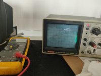
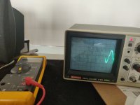
I am also attaching pictures of a 200hz sine on the L & R channels. As you can see the left has this kink (it doesn't appear on the input side but other locations are distorted. This doesn't happen on the R so I am inclined to believe power sections are all fine.
Thank you for your help so far.
I have measured some voltages and marked them up in the attached file.
These are all measured with the -ve on DMM on the left speakers output ground (yes continuity checked)
Also, they are with speaker (L) connected, and no input connected. As mentioned above...the +9v drops to +2 when speakers disconnected.
I am also attaching pictures of a 200hz sine on the L & R channels. As you can see the left has this kink (it doesn't appear on the input side but other locations are distorted. This doesn't happen on the R so I am inclined to believe power sections are all fine.
Thank you for your help so far.
Attachments
the +9v drops to +2 when speakers disconnected.
You show the base of Q615 at plus 9v and the emitter at plus 0.6v.... it doesn't get any more definite than that 😉
Q615 is open circuit base to emitter. There is no doubt based on those readings. Around 0.6 volts is the expected drop across the junction for any silicon transistor. For a NPN the base is the more positive and for a PNP the emitter is the more positive.
The kink you are seeing is a form of crossover distortion.
I would advise setting the bias preset to minimum (which is maximum resistance of the preset) before powering up with a new transistor. Use the bulb to be sure.
Swapped out with a KSC2690AYS and she sings like a dream!
thanks Mooly! Didn't think about it from first principles - I think i was barking up the wrong tree here.
thanks to all those who helped.
thanks Mooly! Didn't think about it from first principles - I think i was barking up the wrong tree here.
thanks to all those who helped.
Actually, this gave me pause for thought.
I went back to the original transistor (it was a 2sd600k). I put it back in, and the amp was clear and the voltages were in spec with the schematic.
I strongly suspect the amp was worked on before, and Q615 was soldered backwards ! That explains all the symptoms.
SO to summarise there were a few issues:
1. Bodged 15A fuse in the speaker section. This was replaced. However, the physically larger fuse had bent the holder, and caused a slight loose contact that manifested itself when i was flipping the amp back and forth for measuring the voltages on the PCB side
2. Scratched trace which needed to be bridged
3. Reversed Q615
Will recalibrate and close it up -- this one was really an interesting project!
thanks again.
- Home
- Amplifiers
- Solid State
- RA 930ax problem on Left channel voltages