When you wind the secondary over the primary you can get better coupling. Not the same thing as leakage.
I think what Pafi is saying is that these are directly related parameters. Flux that doesn't contribute to coupling is defined as leakage. Good coupling, low leakage. Poor coupling, high leakage.
I think what Pafi is saying is that these are directly related parameters. Flux that doesn't contribute to coupling is defined as leakage. Good coupling, low leakage. Poor coupling, high leakage.
I just assumed it was lost in translation. There are trade offs between tightly coupled and loosely coupled primary and secondaries. That is actually one of the issues when designing or specifing a transformer. I have pretty much only designed them for tight coupling. But am aware of a number of loose coupling designs intended for noise reduction.
Of course we could also get lost in discussing the cores used in HF switching supplies. A more specialized design. Last time I got core samples for those the manufacturer actually had to get them from a distributor as they didn't keep any around.
The best examples of loose coupling are some very high voltage transformers. The primary bobbin can be almost a foot away from the secondary on a simple O core. Very thick and well insulated bobbins!
Of course the leakage being discussed in the references was about what left the transformer and interacted with the surrounding components.
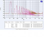
Now one of the interesting things shown in the leakage FFT was the increase of leakage as the secondary was loaded.
Last edited:
Transformer with resistance and leakage reactance | electricaleasy.com
This is called leakage. The flux you referred to by mentioning parts and gaps is generally called stray field, and generated by magnetising current. There could be many things to tell about this (correcting you), but the whole phenomenon is off-topic here. The first is relevant here, since the question was about the coil arrangement on a given core. There were no question about the second, and it is much lower then leakage in case of separated primary/secondary, in loaded state.
Furthermore the logic is simply missing from your "explanation" of denial. Telling "anything can be ruined some way" is not contradictional to the statement "only one way you can do it right".
Exactly. Thanks!
Yes, since it is generated by the coils not occupying the same place. And this is getting worse if you use separated coils. This was may statement.
"noise"? What component? There are 4 very different kind of noise coupling mechanisms at least (if we don't count mechanical/acoustical effects):
1: line transients + primary to secondary capacitance
2: line transients + small leakage
3: load current + high leakage
4: stray flux of magnetising current
Talking about "noise" without mentioning which mechanism doesn't carry any technical information. For example you can defence from line transients by low coupling (both capacitive and inductive), but then you get a higher leakage, and increase load induced noise.
Leakage is not limited to within the transformer, as you already experienced.
This is called leakage. The flux you referred to by mentioning parts and gaps is generally called stray field, and generated by magnetising current. There could be many things to tell about this (correcting you), but the whole phenomenon is off-topic here. The first is relevant here, since the question was about the coil arrangement on a given core. There were no question about the second, and it is much lower then leakage in case of separated primary/secondary, in loaded state.
Furthermore the logic is simply missing from your "explanation" of denial. Telling "anything can be ruined some way" is not contradictional to the statement "only one way you can do it right".
zigzagflux said:Flux that doesn't contribute to coupling is defined as leakage.
Exactly. Thanks!
simon7000 said:Now one of the interesting things shown in the leakage FFT was the increase of leakage as the secondary was loaded.
Yes, since it is generated by the coils not occupying the same place. And this is getting worse if you use separated coils. This was may statement.
"noise"? What component? There are 4 very different kind of noise coupling mechanisms at least (if we don't count mechanical/acoustical effects):
1: line transients + primary to secondary capacitance
2: line transients + small leakage
3: load current + high leakage
4: stray flux of magnetising current
Talking about "noise" without mentioning which mechanism doesn't carry any technical information. For example you can defence from line transients by low coupling (both capacitive and inductive), but then you get a higher leakage, and increase load induced noise.
Of course the leakage being discussed in the references was about what left the transformer and interacted with the surrounding components.
Leakage is not limited to within the transformer, as you already experienced.
Last edited:
Telling "anything can be ruined some way" is not contradictional to the statement "only one way you can do it right".
Just where did you get these quotes from? Or is this another failure to communicate?
Transformer with resistance and leakage reactance | electricaleasy.com
This is called leakage. The flux you referred to by mentioning parts and gaps is generally called stray field, and generated by magnetising current.
Not sure what you are taking away from this reference. The simplified flux picture shows clearly that the flux that is not coupled into the core is modeled in circuit theory as a leakage inductance.
The flux leakage that contributes to this is called Hayward losses in transformer jargon.
They nicely show the flux turning a 90 degree corner. Actually there would be more leakage and even some dispersion effects. (To be sure we are on the same page dispersion is the effect that makes an optical prism work.)
The first is relevant here, since the question was about the coil arrangement on a given core. There were no question about the second, and it is much lower then leakage in case of separated primary/secondary, in loaded state.
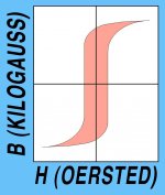
Actually leakage and efficiency do not always follow. The first image is of a center tapped transformer feeding two diodes. Note the unequal amplitudes of the output. In a transformer where the secondary is wound over the primary and is center tapped part way through the winding this will happen. The result is unequal loading of the core on each half cycle. This shifts the operating point on the BH loop (second image.) As you get closer to the edges of the loop efficiency goes down. That is why more modern transformers use bifilar windings so the flux and coil resistance better match.
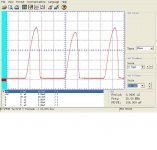
That also brings up the issue of what happens when a core saturates. The farther out you get on the BH loop the greater the leakage flux. The third figure shows the output voltage of a typical small power transformer fed from a sine wave source with less than .05% distortion. Note that there is significant distortion due to mild core saturation. This is of course frequency related. Some constant voltage transformers use this effect to maintain a constant voltage output as the input voltage varies. In this case it does have a bit to do with improving the apparent regulation of the transformer at the cost of increased flux leakage.
Yes, since it is generated by the coils not occupying the same place. And this is getting worse if you use separated coils.
The fourth image is a repeat. Please note that the increase in flux leakage is far greater that 6 dB that would be expected if it were just due to the added coil in the circuit.
"noise"? What component? There are 4 very different kind of noise coupling mechanisms at least (if we don't count mechanical/acoustical effects):
1: line transients + primary to secondary capacitance
2: line transients + small leakage
3: load current + high leakage
4: stray flux of magnetising current
Talking about "noise" without mentioning which mechanism doesn't carry any technical information. For example you can defence from line transients by low coupling (both capacitive and inductive), but then you get a higher leakage, and increase load induced noise.
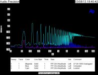
Here we are just completely failing to communicate. I built an AC line noise generator to have a known source of noise to compare how different transformers pass noise. The circuit of the noise generator is shown in the last figure. This noise is of course quite different from that generated by core saturation.
Now although we don't seem to be communicating civilly it still is an interesting exchange. Please feel free to expand on your criticism.
Attachments

Hmmm,
Thanks for all the intel guys, now I'm not sure that what I have is going to work for me. Maybe I'll dissect the R-Core, that way I'll know. I'm still not sure if I can wire it to output 18v while using all windings.
Do I need a rectifier for this circuit? or any other power supply hardware?
Thanks for all the intel guys, now I'm not sure that what I have is going to work for me. Maybe I'll dissect the R-Core, that way I'll know. I'm still not sure if I can wire it to output 18v while using all windings.
Do I need a rectifier for this circuit? or any other power supply hardware?
I am 50 miles from San Francisco, USA. If you mail me your transformer I will map out its windings and figure out the phase dots. I can tell you the voltages and the phasings, but not the currents of each winding; for that you'll need to read the datasheet or perform possibly-damaging electrical tests. I won't do those kinds of tests for you: they offend me. No fee but you will pay postage (and insurance if you want it), both ways.
Its better to maintain symmetry. Left out one of the 9 V winding! But a more important thing is the proper grounding/shielding system. If 1 winding (per leg) is placed between primary and other secondaries, then you may use it as a shield by connecting 1 of their ends to safety earth, achieving much better performance regarding capacitively coupled noise. If you are lucky, 9 Vs are this kind of windings. If you don't see what the winding order is, you can test it directly based on the shielding effect, either with a good AC V meter or with an input of an amplifier. Reference potential of test amplifier must be the same as the shield!First of all, thank you to all. Comprehensive explanations and simple elegant solutions help move things along.
Secondly, there sure are a few different configurations for R-Cores. I probably picked the perfect one to learn on.
With the suggestion to combine the two 18V legs in parallel that still leaves me three 9V .3A sources, can I combine two of those into one, then run that one 9V .6A leg in series with the last 9V .3A winding to get another 18V then run that one parallel with the combined 18V? Or will there be an issue with combining windings of differing amperage?
I'll read up some, thank you Mark for the references.
Do I need a rectifier for this circuit? or any other power supply hardware?
We dont know your circuit. Post a link or attach a schematic!
K.I.S.S.
I have that TOA 500 and am at a loss for how I should use it, there are no 2 identical inputs and therefore I won't get proper stereo sound. Actually there is a huge Billion R-Core and a large EI powering this thing. There are 4 Toshiba 2SC3281's in it but none of it's complimentary sister part the 2SA1302. I'm just starting to learn about this subject but I'm hooked. I'm thinking this TOA is a donor unit, it's intended to be a PA amp and I think all the extra stuff can't be good for clarity.
This is a link to the R-Core and the label on it is as close as I can find to a datasheet.
0?115V Audio 30W 18V 2 9V 3 R Core Transformers for Amplifier DAC Headphone | eBay
or Ebay item number: 251473290530
This is a link to the Pre-amp
New JC 2 Preamplifier Kit Class A Dual Differential FET Input per Amp Kit | eBay
272027400639
I learn more every day and upon looking at the third photo of the preamp, I realized that I built a rectifier circuit on the damn thing months ago. Also, it says Input: 15-20V AC in the specs....nevermind then.
I also bought a torroid with only 18v secondaries just to keep everything simple. I'll put the R-Core to work later.
Actually there is a huge Billion R-Core and a large EI powering this thing.
You're not making sense.
http://www.toacanada.com/assets/files/500-A_Series.pdf
I have that TOA 500 and am at a loss for how I should use it, there are no 2 identical inputs and therefore I won't get proper stereo sound. Actually there is a huge Billion R-Core and a large EI powering this thing. There are 4 Toshiba 2SC3281's in it but none of it's complimentary sister part the 2SA1302. I'm just starting to learn about this subject but I'm hooked. I'm thinking this TOA is a donor unit, it's intended to be a PA amp and I think all the extra stuff can't be good for clarity.
Did you try to look at the manual?
http://www.toacanada.com/assets/files/a-503_506_512a.pdf
It's a mono amplifier. Output transformer is part of the output stage, in center tapped push-pull configuration. Quite old fashioned stuff.
I have close to 10 amplifiers, all but this one are stereo. It was given to me because of the transformers and that is what I'm using it for. I have no use for a PA. Yes I read through the manual and it's exactly what I thought it was. It has the extra microphone module and I don't know what the other one did.
I have that TOA 500 and am at a loss for how I should use it, there are no 2 identical inputs and therefore I won't get proper stereo sound. Actually there is a huge Billion R-Core and a large EI powering this thing. There are 4 Toshiba 2SC3281's in it but none of it's complimentary sister part the 2SA1302. I'm just starting to learn about this subject but I'm hooked. I'm thinking this TOA is a donor unit, it's intended to be a PA amp and I think all the extra stuff can't be good for clarity.
This is a link to the R-Core and the label on it is as close as I can find to a datasheet.
0?115V Audio 30W 18V 2 9V 3 R Core Transformers for Amplifier DAC Headphone | eBay
or Ebay item number: 251473290530
This is a link to the Pre-amp
New JC 2 Preamplifier Kit Class A Dual Differential FET Input per Amp Kit | eBay
272027400639
I learn more every day and upon looking at the third photo of the preamp, I realized that I built a rectifier circuit on the damn thing months ago. Also, it says Input: 15-20V AC in the specs....nevermind then.
I also bought a torroid with only 18v secondaries just to keep everything simple. I'll put the R-Core to work later.
The TOA 5xx series is not a very good amplifier. It is a 1960's design made much later using transformer coupling to the output stage. It is mono and uses an output transformer. The value is in the large R core power transformer, heatsink and other reuseable parts. Either that or as a paging amplifier. As they sell for less than what the transformer would cost they can be a good value.
Here here, it's a very nice R-Core, stout chassis, bridge rectifier/ps board, several descent pots etc. Too big of a case for this preamp project but I'll find something nice to live in it.
Sorry for digging up an old thread. I'm trying to find an appropriate power transformer for a DAC, and because I am familiar with Antek and they're nationally local for me I am biased toward them (toroidal). People have preferences toward R core for DAC's, so I am doing due-dilligence.
Rayma, you talked about connecting secondaries in parallel. Isn't this the typical arrangement for Antek like in this model? AS-0512 - 50VA 12V Transformer - AnTek Products Corp
If this transformer is balanced and employs a static shield between primary and secondary, am I still going to get significant gains with R core?
I'm having trouble finding data or comparison tests
Last edited:
- Home
- Amplifiers
- Power Supplies
- R-Core Crash Course