After spending the better part of a month modelling and building the monstrosity that is 'a simplified transmission line subwoofer' ala Patrick Bateman (thanks again for the guidance John and others), I decided to try out a tapped horn design I had been mulling over for some time.
It's good to compare and contrast, right?
And the reason I did it so soon after finishing one project was because I already had the ingredients for this one 'cut out' from the ruins of the Pipeline. The missus told us this had to go, but in my mind I knew it would return in another way, shape or form. 'Peter would not be told' my art teacher once wrote on my report when I was 10 years old. And she was right.
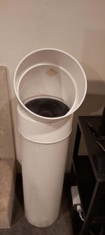
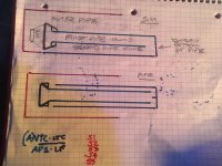
Anyhow, I had this idea for a tapped horn using two pieces of the Pipeline. One is 300mm in diameter or a foot for those still working in the dark ages, and 1m or so in length, which you'd probably call a yard, though we refer to that as the back lawn.
So that's the outer section.
Into that you slide a 1m long 250mm wide second piece of pipe. I'm using PVC here simply because it was to hand. Its original purpose is storm water drain.
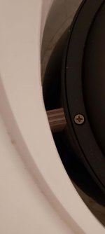
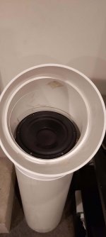
Into the top of the inner section I simply dropped the RSS265HO-44 driver I had available. This literally screws straight in which was completely a fluke. You need to use a gasket of some sort to seal it.
At the bottom end of the outer section you simply block it off with an end cap. But to the inside of that end cap you must add three spacers so that the inner section rests proud of the end cap by an inch or so. I made the gap the same as the distance between the outer wall of the inner tube and the inner wall of the outer tube.
I also inserted three screws into the 1 inch sections of wood so that the inner tube doesn't move around at the bottom end when it's playing.
At the top end, I just made up three wedges of wood to keep the inner tube centred within the outer tube.
Finally, a couple of holes for terminals, and wire up to the driver.
Atop all of this, I had a 30 degree bend that fitted nicely over the top of the outer pipe so it has a hat, and looks a bit more finished.
Ok, admittedly, this isn't the most aesthetic thing I've ever done, but nor is it a complete monstrosity like the plywood TL sub or 3.5m pipeline snake.
I had tried modelling this using HR but really had little idea what I was doing. I did follow Zobsky's Youtube silent movie which was a help and ended up with a tapped horn that had an Fb of 31Hz, but a bit of a droopy response in the middle. The odd thing was when using the LS wizard, it looked pretty good, flattish from about 30Hz to around 100Hz.
Also internal volume was meant to be around 75L and I calculate that my sub plus hat is around 80L, so another complete fluke there.
How does it sound? Well, a bit like classic descriptions of tapped horns. They seem to hit a bit harder in the 35-80Hz zone than designs with which I'm familiar. It's not yet quite as articulate as the big TL monstrosity, but it is only half its size. I had it up and running while watching The Queen's Gambit last night (great show, well worth a look) and the missus either didn't notice the monstrosity was missing or couldn't be bothered commenting on how comely the new sub isn't.
A couple of three pics then.
It's good to compare and contrast, right?
And the reason I did it so soon after finishing one project was because I already had the ingredients for this one 'cut out' from the ruins of the Pipeline. The missus told us this had to go, but in my mind I knew it would return in another way, shape or form. 'Peter would not be told' my art teacher once wrote on my report when I was 10 years old. And she was right.
Anyhow, I had this idea for a tapped horn using two pieces of the Pipeline. One is 300mm in diameter or a foot for those still working in the dark ages, and 1m or so in length, which you'd probably call a yard, though we refer to that as the back lawn.
So that's the outer section.
Into that you slide a 1m long 250mm wide second piece of pipe. I'm using PVC here simply because it was to hand. Its original purpose is storm water drain.
Into the top of the inner section I simply dropped the RSS265HO-44 driver I had available. This literally screws straight in which was completely a fluke. You need to use a gasket of some sort to seal it.
At the bottom end of the outer section you simply block it off with an end cap. But to the inside of that end cap you must add three spacers so that the inner section rests proud of the end cap by an inch or so. I made the gap the same as the distance between the outer wall of the inner tube and the inner wall of the outer tube.
I also inserted three screws into the 1 inch sections of wood so that the inner tube doesn't move around at the bottom end when it's playing.
At the top end, I just made up three wedges of wood to keep the inner tube centred within the outer tube.
Finally, a couple of holes for terminals, and wire up to the driver.
Atop all of this, I had a 30 degree bend that fitted nicely over the top of the outer pipe so it has a hat, and looks a bit more finished.
Ok, admittedly, this isn't the most aesthetic thing I've ever done, but nor is it a complete monstrosity like the plywood TL sub or 3.5m pipeline snake.
I had tried modelling this using HR but really had little idea what I was doing. I did follow Zobsky's Youtube silent movie which was a help and ended up with a tapped horn that had an Fb of 31Hz, but a bit of a droopy response in the middle. The odd thing was when using the LS wizard, it looked pretty good, flattish from about 30Hz to around 100Hz.
Also internal volume was meant to be around 75L and I calculate that my sub plus hat is around 80L, so another complete fluke there.
How does it sound? Well, a bit like classic descriptions of tapped horns. They seem to hit a bit harder in the 35-80Hz zone than designs with which I'm familiar. It's not yet quite as articulate as the big TL monstrosity, but it is only half its size. I had it up and running while watching The Queen's Gambit last night (great show, well worth a look) and the missus either didn't notice the monstrosity was missing or couldn't be bothered commenting on how comely the new sub isn't.
A couple of three pics then.
Attachments
Last edited:
By the by, if anyone familiar with HR can be bothered inserting the RSS265HO-44 T/S figures into HR and figuring out what's optimal for this tube in a tube design, I'd be most grateful. For all I know, this could be miles away from optimal.
But for a first shot without any real sims, it sounds indecently good.
But for a first shot without any real sims, it sounds indecently good.
Maybe Fix droopy with an extended mouth after the tap motor side(flip your driver over you gotta make a smaller initial path diameter), you are now a pvc pipe RoaR or a paraflex (potentially awesome but kinda suits the 265ho4.. you can over lap another larger pipe for a better result,as needed, to support the CSA change and expansion. Kind of pushing accuracy in sim locations, you can create a stub at that point (motor side tap) as well and it seems to get rid of the pesky funk upper bandwidth spikes and junk(especially polyfilled).
Its all in sliding the purple pipe forward or back and sizing it..
I have about two dozen versions for a 12” driver but its Vas its tighter and Qes is a bit lower.. good luck. Read the roar or paraflex threads, a mass loaded exit might be a hole cut in a wooden capped end after a big ‘mouth’ chamber(hint) 🙂
Attachments
Last edited:
A couple of other things:
How much bigger should the purple pipe be in terms of diameter (the larger of the two existing pipes is 1 foot in diameter.
Also, should it be around 100cm long as an initial try-out?
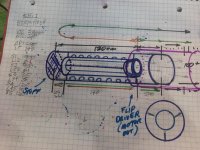
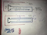
Finally, I cant see where the 140 number in orange comes from. Presumably it is the length of the inner tube and yet at the top the 120cm number in black presumably refers to the outer tube which is longer, so one of those numbers cannot be right (given the inner tube is shorter than the outer tube).
How much bigger should the purple pipe be in terms of diameter (the larger of the two existing pipes is 1 foot in diameter.
Also, should it be around 100cm long as an initial try-out?
Finally, I cant see where the 140 number in orange comes from. Presumably it is the length of the inner tube and yet at the top the 120cm number in black presumably refers to the outer tube which is longer, so one of those numbers cannot be right (given the inner tube is shorter than the outer tube).
Thats just a drawing i had from an old cement tube pillar.. those numbers dont apply to anything rss265..
You gotta use exterior of the one inside the interior of the other for the second pipe and then the next, as the wall thickness is substantial and the turns and driver end adapter/reducer is likely not All sim or gonna fit in tapped horn inputs. with various actual CSAs in multiple folds, etc.
kinda tricky?!!!
Attachments
Last edited:
Please draw a dimensioned sketch as the incomplete description doesn't appear to jive with the pics.
That said, the droop is likely from way too weak a motor for the super high ~352 cm^2 [Sd]/outer pipe's ~38 cm^2 = ~9.2632:1 CR!!
edit: 3:1 CR is about it for any driver most folks can/willing to, afford. From this you can figure minimum outer pipe size.
GM
That said, the droop is likely from way too weak a motor for the super high ~352 cm^2 [Sd]/outer pipe's ~38 cm^2 = ~9.2632:1 CR!!
edit: 3:1 CR is about it for any driver most folks can/willing to, afford. From this you can figure minimum outer pipe size.
GM
Last edited:
GM: The alternative may be to use something like this:
https://solo.co.nz/wp-content/uploads/2020/09/SOLO-DWV-Moulded.pdf (Scroll to the bottom of the page)
In which case the diameter of the internal section of pipe is smaller and the CR reduced?
Or perhaps some holes in the existing internal pipe to reduce the effective CR??
https://solo.co.nz/wp-content/uploads/2020/09/SOLO-DWV-Moulded.pdf (Scroll to the bottom of the page)
In which case the diameter of the internal section of pipe is smaller and the CR reduced?
Or perhaps some holes in the existing internal pipe to reduce the effective CR??
Last edited:
Or another thought; put another pipe within the internal pipe to bring down the CR.
I really rather want to keep experimenting with this design; I've not had such a good response with the RSS265HO in any other enclosure (though the pair of them sealed is pretty decent, but this seems to have more potential). It just feels/sounds like it could be better with a bit of judicious/random tweaking.
I really rather want to keep experimenting with this design; I've not had such a good response with the RSS265HO in any other enclosure (though the pair of them sealed is pretty decent, but this seems to have more potential). It just feels/sounds like it could be better with a bit of judicious/random tweaking.
Hmm, I was more tired than I thought and no one caught my glaring error. 🙁
Using pipe effective areas instead of last night's diameters, the inner pipe's ~490.87 cm^2/ 532 cm^2 [Sd] = ~1.084: 1 CR and the large pipe's ~162.85 cm^2/532 cm^2 [Sd] = 3.267:1 CR
CR is a little over, but for home use probably OK, not that it matters though if I got a 'close enough' sim [PiP] just using enough space behind the driver to seal the big pipe and ignored the added elbow. What you're hearing is the exact opposite, so ATM no clue where I screwed up this bad. 🙁
For reference I did a basic TH [BTH] and a DSL's 1/4 WL offset driver [DTS], which implies getting something close with PiP seems remote unless 'we' can figure out this huge discrepancy.
GM
Attachments
GM: The alternative.....some holes in the existing internal pipe........
??? I don't follow......
It's the outer pipe making the CR, so not an option.
GM
OK, I see my mistake. I actually had it right in my mind the first time, but couldn't make it work, so inverted to get a terminus [mouth]. Guess one of the new fancy BP wizards will work, but haven't messed with them yet, so will let BW do the sim.
GM
GM
Hmm, TH = 6th order series BP and believe I was the first to state this, so had a major 'senior moment'.
This replaces the first PiP HR file, so at least the schematic looks right [to me] less the elbow, but still falls well short of your build, i.e. is tuned to ~50 Hz, so still missing something as I seriously doubt the elbow would make this much difference.
GM
This replaces the first PiP HR file, so at least the schematic looks right [to me] less the elbow, but still falls well short of your build, i.e. is tuned to ~50 Hz, so still missing something as I seriously doubt the elbow would make this much difference.
GM
Attachments
Or another thought; put another pipe within the internal pipe to bring down the CR.
I really rather want to keep experimenting with this design.......
Again, it's the outer pipe dictating its CR.
Then get a smaller 140 mm pipe over the driver to create the CR. This will open up the big pipe to ~505.3 cm^2, so ~1.435x the driver's [Sd] I used for the TH sims, but makes little difference compared to the 6th order sim of yours and of course the real problem is the pipes need to be ~3 m longer to tune it down below Fs where it needs to be.
You can nest more pipes, but some will need to be [much?] bigger to get the length/flare.
GM
I just could not for the life of me understand where the 38cm2 came from, and puzzled over it for some time, giving up and not questioning it...cos I had other stuff to do, like work.
Anyhow, tonight I arrived home and immediately turned the driver to motor out.
I also stuffed a smaller pipe inside the inner pipe, decreasing the CR somewhat? Otherwise, all is the same.
The sub is definitely sounding better, more of everything. By happenstance, I listened to two reasonably bass heavy favourites that came up and was stunned at the improvement...but then had to go out for dinner. Tomorrow I will remove the inner pipe and have another listen, just to sort out whether it was the motor out change, which Im expecting it is. But this 10-inch driver is hitting as hard as anything I've made before, and is sounding so articulate.
It's a complete surprise that something that took so little time to make can sound so convincing. So thanks both to GM and BW for your input, it is sincerely appreciated.
Will check out the sims on Monday using work computer (dont have HR at home, unfortunately).
I have one question: why is it that using the LS Wizard I can get a nice flat response for the TH, and I save that but when I push the recalculate tab, the power response looks all droopy in the middle again (from about 40-80Hz)?
All i have in Sonotuuupuube is 335/356, 531/560 and 774/824cm2 at 122cm lengths(inside and outside). I dunno what they have besides a didgeridoo for pipes in OZ? 😛
I had a sim for that driver was ~250 cm2 for 330-350cm or so... sonehow got wiped out when i updated the horn resp program earlier 🙁
I had a sim for that driver was ~250 cm2 for 330-350cm or so... sonehow got wiped out when i updated the horn resp program earlier 🙁
Hi BW
Do you mean 250cm line length?
Also, for what it's worth, I live in New Zealand which isn't the same as Oz. They lie 3000km to the west. Just saying.
And yes, we can get the cardboard tubing here called by 'the name that must not be mentioned'. Only, I prefer to work with PVC. It is more rigid, and much easier to do endcaps for. You just make the circles a touch bigger, sand them down, and smash them home. They seal well and simply do not move.
GM: I intend to follow up with your nested pipes idea further.
I was under the probably misguided impression that TH lines are generally shorter than for TLs and you don't aim for Fs?? And perhaps that's because in a TH it is easier to run into over-excursion problems?? But I may well have got this wrong.
Anyhow, I'm aiming to replace the end joiner with another bigger external pipe today and that should take the line length to at least 2.5m, actually closer to 3m.
Oh, and by the by, I have enough materials on hand to construct another one of these for the other RSS265 I have sitting here lying idle.
With subs, two is better than one, right?
Last edited:
Oh, new zealand? Nice! Whats a ‘3000km’? in ‘yards’ haha😛
..that was actually 248 cm2 at 354cm based on a generic qw pipe for Vas and Fs(and (0.45Qts)). Its not necessarily ‘perfect’, but its not a blind guess either. if you used that, and slightly smaller CSA splitting the ‘qw pipe’ section at the ‘fold’, then any ‘mouth/exit’ after the driver could be 400-450cm2 if its the same outside diameter pteviously sleeved in a folded two pipe concevtric TL path. But you need to clear a 352cm2 driver thats likeky much morethan 400cm2 mounted and attached to the inside pipe already...?? i dunno, and we have 12” cardboard here, 3000km from Canada or Mexico, 😀 its 775cm2 or so measured. And 400 is left inside 400(350id) cm2 is stuck inside it as a folded qw pipe.
Tell the wife its a disease and she must accept whatever it ‘looks like’. then you can build the necessary ‘tapped pipe’ or ‘pipe with a driver slightly inside the mouth’. Those are not the same thing, nor do they perform once they arent. Roar might be obvious, but its as soon as that's obvious.(stick it in farther until you notice) that you realize its a bunch of things? i dont care about names, thats a new type of sound. its my ears saying so, nothing else. Its there once you hear it, youll be hooked, and puzzled forever(if you liked anything about it to start).
- Home
- Loudspeakers
- Subwoofers
- Quick and dirty tapped horn