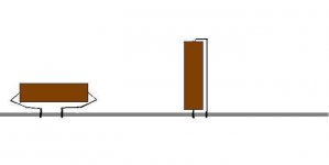
Sometimes when substituting a larger, higher-quality component, (such as a resistor or capacitor) there isn't room to lay the component against the board (example: when the pcb holes are close together), making it necessary to bend the leads under a cap, or stand a resistor up on end...
For lowest noise pickup , is it better to to wrap both leads around/under to fit, or to stand a component on end?
Also, when standing components (e.g. resistors) on end, which lead should be shortest (soldered closest to the board)- the the input (or "hot") end, or the output (or GND) end(again, for lowest noise pickup)??
T.I.A.,
-Joe
Attachments
I don't know what you mean with noise pickup? I assume you use anyway a metallic case, so interference should not be a problem.
Overal noise in an amp is not affected by your suggestions, other sources like transistors or megaohm resistors, also bad wiring (e.g. too close to transformer) dominate the sources you mention easily by a huge factor - not to mention bad pcb-layout. No way you can affect total noise with your measures.
Maybe you want to read a bit about thermal noise (resistors) and its magnitude compared to active parts?
Have fun, Hannes
Hi,
I think the larger component will be more susceptible to picking up interference.
I think he is right to ask.
I recently read that the orientation of SMD resistors and capacitors makes a very significant difference to the parasitics that affect performance. SMDs have tiny loop areas compared to discrete, particularly the BIG discretes.
I associate parasitics only with pcb-layout and in this case orientation of course can matter (however more due to different trace layout), especially in the RF-range.
Honestly, if one has to consider this lead orientation issue seriously, one should - in my opinion - immediately revert to smd-parts. A lot less parasitics for free 😀
But I look forward to get corrected!
Anyway, I had the impression that the original posting was more targeting at tuning methods which might not always be proven to really improve things 😀 Like stripping the vinyl-sleeve off caps. However everybody should feel perfectly free to try whatever he or she wants.
Have fun, Hannes
In my query I neglected to mention that the aforementioned upgrades are to the audio section of a DVD player, where there is digital circuitry (not to mention video circuitry) nearby.
As the original resistors are 1/8W axial M.F. type, and are being replaced with 1/2W Riken Ohms, there is no option to use SMD's.
If anyone here has used resistors in the vertical(i.e. standing up) orientation, have you given any consideration to which lead is exposed and which is placed at the pcb??
-joe
jtsaudio said:In my query I neglected to mention that the aforementioned upgrades are to the audio section of a DVD player, where there is digital circuitry (not to mention video circuitry) nearby.
As the original resistors are 1/8W axial M.F. type, and are being replaced with 1/2W Riken Ohms, there is no option to use SMD's.
If anyone here has used resistors in the vertical(i.e. standing up) orientation, have you given any consideration to which lead is exposed and which is placed at the pcb??
-joe
Hi Joe
Indeed your query it is very unusual and amazing. I acknoweledge that never i thinked this case. With the appropriate reservation and from my experience, i think that in the vertical orientation it is most prefferable to expose the lead oriented to the lower voltage level (i.e. gnd) which has the importance that the node which presents the lower impedance, it is most insensitive in ambient electromagnetic fields. An example it is the signal cables. As you know, in the external cover of metalic RCA or Jack plugs it is soldered the gnd conductor and not the signal conductor. Ah? Do you think that this is not a logical assumption?
Fotios
jtsaudio said:In my query I neglected to mention that the aforementioned upgrades are to the audio section of a DVD player, where there is digital circuitry (not to mention video circuitry) nearby.
As the original resistors are 1/8W axial M.F. type, and are being replaced with 1/2W Riken Ohms, there is no option to use SMD's.
If anyone here has used resistors in the vertical(i.e. standing up) orientation, have you given any consideration to which lead is exposed and which is placed at the pcb??
-joe
The exposed lead that sticks up, I've always tried to use on a connection that isn't as dangerous to short.
Any resistor to ground, I have the ground longest, and the short end in the PCB.
Any high impedance connections if possible go on the PCB side of resistor.
Also, if you are able, (if the part fits) I think your 1st method is better where each lead is the same length and wraps underneath. Sometimes you can't always have the room to do that, so expose the least crucial connection like in my prev post.
Thanks for the responses thus far...
I'm surprised that I couldn't find references to this in my searches, so that's why I posted. Another fellow had asked me about this and I couldn't say for sure and that's why I'm putting this question out there.
Any other opinions/experiences?
-Joe
I'm surprised that I couldn't find references to this in my searches, so that's why I posted. Another fellow had asked me about this and I couldn't say for sure and that's why I'm putting this question out there.
Any other opinions/experiences?
-Joe
If using tubular polystyrene caps the coloured or "stripy" end is the outer of the foil. Connect this to the lowest impedance part of the circuit and get benefit of shielding, even more important if using on high gain stages. Rotating toroidal transformers worthwhile to find the lowest radiated magnetic field that interacts with phsical layout of P.C.B.
Regards Karl
Regards Karl
I think I've got it!
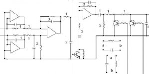
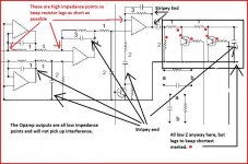
So I'm understanding that when standing our resistors we should ideally keep the "input" or "hot" lead (a) down toward the PCB and the "out/gnd" lead ( b) up? Would this be the case for resistors when used in positions 1, 2 & 3 in the attached diagram?
And when standing (tubular) caps, the striped end should ideally be the "input/hot" lead (a) oriented downward, and the other, "output or Gnd" end ( b), should go upward? Would this be the case for capacitors when used in positions 1, 2 & 3 in the attached diagram?
Attached diagram is an example of a circuit application .
Again, any input is appreciated, as I'm trying to understand this more fully.
-Joe
"Any resistor to ground, I have the ground longest and the short end in the PCB. Any high impedance connections if possible go on the PCB side of resistor."
So I'm understanding that when standing our resistors we should ideally keep the "input" or "hot" lead (a) down toward the PCB and the "out/gnd" lead ( b) up? Would this be the case for resistors when used in positions 1, 2 & 3 in the attached diagram?
"...the coloured or "stripy" end is the outer of the foil-Connect this to the lowest impedance part of the circuit
and get benefit of shielding."
And when standing (tubular) caps, the striped end should ideally be the "input/hot" lead (a) oriented downward, and the other, "output or Gnd" end ( b), should go upward? Would this be the case for capacitors when used in positions 1, 2 & 3 in the attached diagram?
Attached diagram is an example of a circuit application .
Again, any input is appreciated, as I'm trying to understand this more fully.
-Joe
Attachments
- Status
- Not open for further replies.
- Home
- Amplifiers
- Solid State
- Questions re: component orientation for lowest noise?