Oh yes, I will be mounting the fuse and all inside the amp behind the speaker, the only thing accessible from the outside will be the power switch, and that will be mounted in the wood. I am just testing at the moment, so mostly just using the headphone out from an old radio no-one gives a shyte about any more. And the earth will be hooked up before I let this thing off the test table of course!
I was wondering WHERE to hook it up, exactly, so earth on the jack makes sense as a last line of defence. Aussie standards might even be just a little bit stricter than American when it comes to this sort of stuff because we use 240v mains and that stuff is just not a joke! I might even put car fuses in the 12/24v side of things just for an extra layer of safety! Last thing I want is a live guitar! So if the fuse goes she will be calling me for a service, and I will do some tests, it is my first amp build after all!
The long term plan was to get a decent box (the speaker enclosure sounds really good) with a good speaker (100w PA speaker is no joke!) so that later, as I improve and actually start making my own amp designs I can rip the guts out and make it sound like a really nice amp! For now she has the pocket pod and a little bit of tube flavour. If I can get it all working this week that is!
I will pass on the youtube picks and probably take a gander myself as I do like me some live music from a talented artist! Cheers for that!
Will be testing from back to front in the morning and I will post any extra pics etc with my findings, let us pray for good news! (I'm atheist, don't bother praying haha) Me and Spock will logic our way through! (also not really a trek nut lol)
Edit: Happily listening to that 2nd link now! Awesome! And the other one, while not really my kind of music, she is still awesome and I will be passing that one on for sure as well!
Also, since the pre made tone circuit STILL hasn't arrived, I was hoping maybe you could have a glance at my crappy one and just see if I have followed the diagram correctly? Thanks again and in advance again!
Last edited:
I usually bond it to the metal chassis (solder or secure physical connection with a bolt and toothed washer), bond the transformer's metal body to the same spot, and bond the negative leg of the main power supply filter capacitor to the same spot. Since that same negative end of the filter capacitor connects to the ground wiring of the entire amplifier it's powering, that takes care of grounding the input jack....I was wondering WHERE to hook it (earth) up, exactly
I've been bitten by 240V AC, and I agree, no joke! I was a teenager with a strong heart then, and got lucky. Today? I might not survive such a strong shock....we use 240v mains and that stuff is just not a joke!
Neither of them is really my kind of music, but as you say, these are all awesomely talented and skilled musicians. I thought it might do your young niece some good to see women guitarists who can play rings around most men, not just sing pretty songs while some dude has to play all the complicated guitar parts for them. 🙂Edit: Happily listening to that 2nd link now! Awesome! And the other one, while not really my kind of music, she is still awesome
I did look at your pic right after you uploaded it, but I couldn't understand it, it gave me a headache and I was left sobbing for my mommy. 😀I was hoping maybe you could have a glance at my crappy one and just see if I have followed the diagram correctly?
I'll give it another shot later today, once I've recovered from the trauma. 😀
-Gnobuddy
I tried, but was reduced to traumatized tears and calling for my mommy once again, so I gave up. 😀...see if I have followed the diagram correctly?
But I drew up a layout for you that is (a) very simple, and (b) needs no PCB at all, as you can solder the few components directly onto the potentiometer lugs.
In the attached image, I've assumed we're looking at the potentiometers from the back, i.e., the potentiometer shafts are pointing away from us, into the computer screen.
Some of the component values are very peculiar, and not standard values at all, but if you say you already have them, then so be it!
Oh yeah, the pot on the left is the bass control, the one on the right, treble. Ignore the "Linear" text on the pots, use whatever you were planning to; this particular type of tone control behaves poorly with both linear and log pots, so there is no good choice!
I have omitted the 1M resistor (R5 in your schematic) - it is usually the grid bias resistor for the next preamp valve, not part of the tone control itself.
I hope this helps!
-Gnobuddy
Attachments
I tried, but was reduced to traumatized tears and calling for my mommy once again, so I gave up. 😀
But I drew up a layout for you that is (a) very simple, and (b) needs no PCB at all, as you can solder the few components directly onto the potentiometer lugs.
In the attached image, I've assumed we're looking at the potentiometers from the back, i.e., the potentiometer shafts are pointing away from us, into the computer screen.
Some of the component values are very peculiar, and not standard values at all, but if you say you already have them, then so be it!
Oh yeah, the pot on the left is the bass control, the one on the right, treble. Ignore the "Linear" text on the pots, use whatever you were planning to; this particular type of tone control behaves poorly with both linear and log pots, so there is no good choice!
I have omitted the 1M resistor (R5 in your schematic) - it is usually the grid bias resistor for the next preamp valve, not part of the tone control itself.
I hope this helps!
-Gnobuddy
I'm sorry I made your future great grandkids cry with my crappy circuit design, I almost literally copied the circuit but bent it around to have all the ins and outs on one side and then realised one or two places where tracks would touch and had to cross, so hence a couple of stray wires, also the black heatshrink in the middle right is covering a couple of caps in parallel to get the right value. The series resistors are there just because the pack I bought didn't have every single value so I had to pick a couple of lower ones to series up and get what I needed.
Great to know I don't need the 1 meg resistor, it said load resistor so I assumed it was impedance loading on the output, I'll take it out if it's just for bias I don't need, though that output IS going back into the tube amp, I am guessing the circuit around the tubes makes the whole thing act more like a FET amp as far as the signal goes. I'll give your pots circuit a go I reckon, if that bloody tone board doesn't show up today anyway! If it does expect a quick question to confirm which way to change the cap value on the treble pot to suit guitar better! XD I'll look it up first don't worry.
one more quick thing, I found this 12ax/au pre board cheap with what looks like better components, of course I have to get the ax tubes but I have 2 already as my vox tonelab uses them, and I can get them at wholesale price here. Would this be a better choice for a guitar pre? Of course I want to IMPROVE the quality of any future amp builds! I am trying to get to a place where I feel comfortable selling whatever I come up with in the future!
Low Distortion Tube Preamplifier Preamp Board DIY Kit fit for 12AX7 / 21AU7 Tube 699916488455 | eBay
Low Distortion Tube Preamplifier Preamp Board DIY Kit fit for 12AX7 / 21AU7 Tube 699916488455 | eBay
Last edited:
another quick question, as I said I am testing with a headphone out from a radio. Should I add a resistor to first input on the pre to jack up the impedance to the up to 1M typical humbucker out from the guitar? maybe a 10M? and if so, should it go in series or parallel? I would think series would kill the signal, parallel also seems kinda counter productive though! The most confusing thing about all of this is, how do I figure out the input and output impedance of the amps? Is it just the specs on the chips or would the parts in the board matter more? Every time I search for this topic I get a headache of math! I might have to study, like a lot!
Oh, and to put your mind at ease, I am getting a 2A resetable panel mount breaker from a reputable aussie wholesaler to mount in the chasis, I don't trust the chinese power supplies to break safely any more than you do! I might keep the 2A fuse as double backup, but that's probably not needed with the earth etc, we all have RCD's by law in our house fuse boxes these days, so any earth leak will trip that sucker faster than you can say......
...love making red tape almost as much as the French.Aussie standards might even be just a little bit stricter than American when it comes to this sort of stuff because we
Short answer: ensure any exposed metal (or single insulated metal) is attached to the earth stud at which the incoming earth terminates.
Even shorter answer: use a COTS stepdown transformer with an RCM and then blame someone else.
See, now you know why I couldn't figure out your build. You cleverly disguised every part of it. 😀 And then you hid the pots off the edge of the photo for good measure!...bent it around...stray wires...black heatshrink...covering a couple of caps...series resistors...

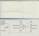
It's the bass control that's very wimpy at the moment. See attached image - the red line is both pots set to the middle, so as you can see, there is very little bass cut available....which way to change the cap value on the treble pot to suit guitar better!
I expect the culprit is R3, much too small at 5k. I think R3 should be one-tenth the value of R4, but R4 seems too big (300k) compared to the value of the pot (500k). I think the reason bass boost is also wimpy compared to treble boost is because R4 is too big.
300k, 5k, and 6nF are non-standard values, so you'll always have to make them up using series and parallel combinations of resistors or caps. 270k, 4.7k, 5.6nF, and 6.8nF are all standard values, and I would think those are quite close enough to the values you used.
(But don't switch to those values yet; I think it might be possible to produce some better bass curves with a little parts tinkering.)
-Gnobuddy
Attachments
Not as-is. "Low Distortion" is the last thing we want for guitar!Would this be a better choice for a guitar pre?
<snip>
Low Distortion Tube Preamplifier Preamp Board DIY Kit fit for 12AX7 / 21AU7 Tube 699916488455 | eBay
But if you omit R4, replace R6 with a wire link or zero-ohm resistor, solder a 2.2uF cap across R5, reduce C2 to 4.7nF, install a tone-stack between the two points where C1 is supposed to install (don't install C1), increase R7 to 1 Meg, solder a 10uF cap across R8, and replace the right-most resistor (marked 623????) with a master volume 1 Meg log pot, you will have something that kinda sorta works for guitar.
So, basically, if you throw away their schematic, re-design the entire circuit, and force the new circuit awkwardly onto a PCB that wasn't designed for it, you'll have something usable for guitar! 😀
(It is entirely possible to build the modified circuit as I've outlined above onto this PCB. You'll have to solder the 2.2uF and 10uF caps either underneath the PCB, or directly onto the tiny bit of wire lead emerging from the ends of R5 and R8. Quite do-able.)
Heck, for that price, I'm almost tempted to get one of these boards and hack it to turn it into a two-channel guitar preamp (it's a stereo board, so there are two channels already on board!)
-Gnobuddy
Last edited:
I have the impression the English invented mind-numbing and totally crippling red tape, then imported it to every country they subjugated by force. I have personally seen it in action in India and Canada, got first-person reports from family friends who emigrated to Nigeria, and now you say it's alive and well in Australia as well. Betcha it's in all the former English dominions too. (Charming word, "dominion", is it not?)...love making red tape almost as much as the French.
To be clear, I do not hold any grudges against the English of today; the past is gone, and England was hardly the only country to have, at one time, enjoyed trampling all over millions of conquered people all over the world. But we should not forget those ugly historical facts, because there are still those in power who enjoy bullying and browbeating, and would like to repeat history if they could.
-Gnobuddy
No. Adding any large resistance here will make your amp go "hissssssss".Should I add a resistor to first input on the pre to jack up the impedance to the up to 1M typical humbucker out from the guitar?
The input impedance of your valve preamp will normally be set by the input valve's grid bias resistor. Without knowing the schematic of your existing valve preamp, that's the best I can do. If you have the schematic (or a link to it), please post it, and then I should be able to tell you more.
It is a good idea to add something like 10k in series with the input, not to change the input impedance, but to help filter out any radio frequency interference that is picked up by the guitar and guitar cable, so it doesn't get into your preamp and ruffle the valve's feathers. Hi-Fi preamps don't need this, because they don't usually have fifteen feet of coaxial cable tipped with a poorly shielded inductive guitar pickup hanging off the input!
-Gnobuddy
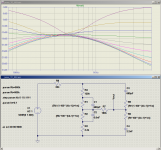
Here's a somewhat better-behaved version of the passive James tone control. Bass control response, in particular, is considerably improved.
Both pots are 500k log (470k in some countries.) All resistors and capacitors are standard values.
As you can see from the unevenly spaced curves, the James control responses aren't particularly progressive. (But they're still a lot better than the bizarrely unfriendly tone control Fender used on many of his classic valve guitar amps.)
In my limited experience, the James tone control can make a guitar amp sound a bit midrange-dominant; actually it's the opposite, our ears expect the midrange to be scooped out, a la Fender Blackface amps, and the James doesn't have that mid scoop.
-Gnobuddy
Attachments
It's been creeping up for at least the last 40 years, on one hand driven by the safety mantra and on the other by an unsubtle effort to replicate the "closed shop".....and now you say it's alive and well in Australia as well.
Every year there's another thing I'm no longer competent to do and I need to do another certificate in something and/or document several years of supervised experience (signed off by an existing licensed practitioner).
Worse, much of it results in "busy work" and box ticking, often duplicated (you need a gas plumber and an electrician and a telecoms tech to install your internet connected water heater - if it has a camera you may need a security license too). But I get to make money advising people on which pieces of paper and what specialist trades they need 🙂. It's certainly easier than, you know, actually helping them be more productive or less risky.
Only in the most blatant cases do we get any push back (e.g. the QLD rules on solar panel installations)
Not as-is. "Low Distortion" is the last thing we want for guitar!
But if you omit R4, replace R6 with a wire link or zero-ohm resistor, solder a 2.2uF cap across R5, reduce C2 to 4.7nF, install a tone-stack between the two points where C1 is supposed to install (don't install C1), increase R7 to 1 Meg, solder a 10uF cap across R8, and replace the right-most resistor (marked 623????) with a master volume 1 Meg log pot, you will have something that kinda sorta works for guitar.
So, basically, if you throw away their schematic, re-design the entire circuit, and force the new circuit awkwardly onto a PCB that wasn't designed for it, you'll have something usable for guitar! 😀
(It is entirely possible to build the modified circuit as I've outlined above onto this PCB. You'll have to solder the 2.2uF and 10uF caps either underneath the PCB, or directly onto the tiny bit of wire lead emerging from the ends of R5 and R8. Quite do-able.)
Heck, for that price, I'm almost tempted to get one of these boards and hack it to turn it into a two-channel guitar preamp (it's a stereo board, so there are two channels already on board!)
-Gnobuddy
IKR? Bloody good price on that pre board and the pic looks like decent parts supplied as well! If I go for that I will most certainly be using this post for modifications! Awesome! Thanks so much!
Haha, I'll have you know that pickup cavity is shielded! At least, from the back! XDNo. Adding any large resistance here will make your amp go "hissssssss".
The input impedance of your valve preamp will normally be set by the input valve's grid bias resistor. Without knowing the schematic of your existing valve preamp, that's the best I can do. If you have the schematic (or a link to it), please post it, and then I should be able to tell you more.
It is a good idea to add something like 10k in series with the input, not to change the input impedance, but to help filter out any radio frequency interference that is picked up by the guitar and guitar cable, so it doesn't get into your preamp and ruffle the valve's feathers. Hi-Fi preamps don't need this, because they don't usually have fifteen feet of coaxial cable tipped with a poorly shielded inductive guitar pickup hanging off the input!
-Gnobuddy
Awesome to know though. So the 10k would make hiss in parallel then I am guessing. Will do the series thing.
I tested today with one side of the pre and the power amp with the pocket POD plugged into a 9v wall wart, I also went back to the 12vac wall wart for the pre as the other one seems to cause too much noise. I might have to get a decent toroidal or something for future upgrades.
I forgot to mention, the actual 24v main power supply for the power amp is earthed, the bare earth wire is for hooking up to the shielded box I plan to make for the actual electronics to sit in, inside the amp of course. Would you recommend that I add an earth wire to the earth rail on the preamp, hooked up to the chassis? It is the only thing that won't have earth from the power pack as it only has 2 prongs.
Anyway, I got a little buzz and noise, the tubes are a little microphonic and I get a slight ring when I touch the volume knob on it, but overall the sound is pretty damn good all things considered! I assume a lot of the noise will go away when it is inside an earthed enclosure. Well, I HOPE so anyway because that is final stages of the build!
My main problem is that the volume knob on the pre goes from 0 to 11 in the first 5th of a turn! (17 watts in a quality 8 inch speaker can get LOUD!) I may have to replace the pot (It's crap anyway) and put a separate switch in for turning on the pre, I am thinking a resistor in line with the pot, but I am guessing the 10k resistor in line will probably pull the input down anyway. Tomorrow will be time to try all of these suggestions one by one I reckon, I'll nut this thing out and make a quiet amp yet!
I'll check in tomorrow before I start messing around in case there is any more gold in here! Cheers!
Oh I also purchased 10 more of the 6j1 tubes for about AU$12 and 2 more preamps for about $18, I plan to swap tubes out in a built pre and find the ones that aren't so damn microphonic! I will have to shock mount the pre as it is! Lucky I was already planning to move the pot to the chassis and off the board to use as the volume control, since the amp doesn't really heat up anyway, it should be fine running cranked at 18 volts or so while the amp is on. I also plan to (somehow) implement the mute switch pads on the amp board to a button or switch so that the speaker doesn't get the pops at on and off times. If she plays her cards right she should be able to use this speaker and cab for years to come!
Found one. This is the pre I have, down to the same shitty green volume knob.
6J1 Pre Schematic - Album on Imgur
Another edit: looking at the schematic, I am not so sure, 230v to the plates on the tubes? I think this only runs about 30v +- max at any given point in the circuit! If I am looking at it correctly, looks like at least the schematic in the pic as a 1k grid bias?
Oh and that tone stack is almost exactly curve that the stock one makes in tone stack calculator! I think I'll hit up the wholesaler again for a few pots at better values and log type. And I HAVE to go with a James tone stack. It is LITERALLY my middle name! XD
Last edited:
Dammit, I was right, don't know WHAT that circuit is doing with that board other than to dupe people into thinking that the tubes run at high voltages!
Actual 6j1 pre schematic - Album on Imgur
Here ya go. Looks like 4.7k to me?
Actual 6j1 pre schematic - Album on Imgur
Here ya go. Looks like 4.7k to me?
That's the grid-stopper. Good, you have a 4.7k grid-stopper, so there's no need to add an external 10k in series with the input.Here ya go. Looks like 4.7k to me?
You have a 470k grid bias resistor, too low for a humbucker input, needs to be changed out to 1 meg.
50k volume pot (!!!), very bad for your purposes, this has to be removed from board or copper traces cut to disconnect the pot from valve control grids.
50k is twenty times too low - it will suck the guitar signal down to nothing, and also load down your James (sometimes called passive Baxandall) tone control so much that it won't work, either.
It is quite possible that this 50k volume pot is single handedly causing the problem you've been hearing (nothing but buzz, and no guitar signal.) The pot has to go.
I assume it's a stereo pot (six pins soldered to the PCB). It will be a challenge to remove, but it can be done with a solder-sucker, desoldering braid (copper wick), a good soldering iron, and lots of patience. It may be simpler to cut the two traces running to the valve control grids.
The attached image shows what's needed.
-Gnobuddy
Attachments

- Status
- Not open for further replies.
- Home
- Live Sound
- Instruments and Amps
- Questions on a hobbled together amplifier I am trying my hand at.