That's the grid-stopper. Good, you have a 4.7k grid-stopper, so there's no need to add an external 10k in series with the input.
You have a 470k grid bias resistor, too low for a humbucker input, needs to be changed out to 1 meg.
50k volume pot (!!!), very bad for your purposes, this has to be removed from board or copper traces cut to disconnect the pot from valve control grids.
50k is twenty times too low - it will suck the guitar signal down to nothing, and also load down your James (sometimes called passive Baxandall) tone control so much that it won't work, either.
It is quite possible that this 50k volume pot is single handedly causing the problem you've been hearing (nothing but buzz, and no guitar signal.) The pot has to go.
I assume it's a stereo pot (six pins soldered to the PCB). It will be a challenge to remove, but it can be done with a solder-sucker, desoldering braid (copper wick), a good soldering iron, and lots of patience. It may be simpler to cut the two traces running to the valve control grids.
The attached image shows what's needed.
-Gnobuddy
AWESOME to know! I made the board from a parts kit, and I have all the tools to desolder, no problem, I was planning on taking it out anyway to replace with one mounted in the chassis and a separate switch. Might even put 2 separate pots in if I keep the double gain stage and don't just go with one channel, so I have 2 gain controls.
I have a bag of 500k linear taper pots, and I purchased a few selected values of new alpha and CTS pots from the wholesaler that should be here by friday as well. But by the sounds of it the 500k pots with maybe another 500k resistor? Might mean half volume but really, it's way too sensitive as it is! Should do the job at least for testing. I do believe I have a couple of 1M pots coming, either alpha or CTS, seriously, I can get alpha pots for about AU$2 and CTS ones for under AU$5! I bought about 30 bucks worth yesterday just for decent parts for a change! XD Cheapest Alpha pot on ebay is like 10 bucks alone! I would hate to see retail price for the CTS ones!
I had a little jam on the amp last night, I get a high pitched noise when playing through the pocket POD but my ESP LTD plugged straight in I have to say has a nice clean sound! I assume the POD is noisy because of the PSU, and I have one coming designed for quieter power out, if that is still noisy I will tell her to use batteries and when I get the couple of 50v filter cap boards I ordered (There is one already in the amp before the power amp stage filtering the 18v from the buck converter) I will make her a quieter power supply by fitting that inside the amp with a plug out. It looks like the amp will have a power board inside it at this stage, lots of wall warts otherwise to power everything!
I am thinking of adding one more volume knob on the signal wire between the pre stage and the power amp stage because I reckon the tubes will actually distort but the amp would be so loud as to be unusable for practice. Would a 500k pot do there as well you reckon?
Would I be better off cutting the voltage to the amp to lower the volume or cutting the input signal with the pot? I am torn because cutting the signal leaves the cranked power amp with a small amount of noise, where cutting voltage would decrease both. And lastly, if cutting the voltage is the best way, what would you recommend to do this? the pot on the buck converter is TINY and I don't know its value, or I might try to solder wires in its place and fit an actual pot to it! Then I can use that to cut the voltage down to something like 3v if need be!
And yes, actually I got Tone Stack Calculator because I was googling tone stacks, came across the Bandaxall and wanted to make one, and TSC seemed the easiest way to proto it before building. Of course it took me another google search to find out it was the James stack as well with a slight mod or two!
Don't worry, I have been doing literal months of research watching youtube videos, doing my own searches, most of which lead to this very forum, which is why I joined!
I have a (fair) grasp of the actual physics, in a perfect vacuum at least, It's just the real world side of things and some of the electronics (complicated circuits in particular) that I am catching up on really. You may assume that I know how to solder and such in future, I probably should have mentioned that! Sorry!
Anyways I'm off to change out some resistors, remove the 10k I added yesterday which I know now why it didn't seem to do much!
Oh and the guitar is also fitted with 500k pots, just so you know where the signal is coming from, but if it goes through the pocket POD I don't know how it loads the signal, it's basically a multi effects processor with a headphone/aux out on 3.5mm and an amp out on the 6.5mm jack. (thank gawd you're Canadian and not from the US, I cannot be arsed converting that right now, except to say I do know the 6.5 is quarter inch standard guitar jack) 😀
Just one more brain pick, the input impedance is set by that grid resistor, coolio! which one sets the output impedance? I would just like to make sure that I have at least 10x more out than in is all, as I hear that this is best practice for solid state power amps and audio connections in general.
Thanks again for the tips, you have been an awesome help with those gaps in my knowledge so far!
oh also, this is the page where I got the schematic.
6J1 Pre-amp modifications (hum removal))
There was a hum removal mod on there which I did last night (found a 400v 470uf cap in a dead 12v wall wart from my old job) but I'm not sure it did very much, possibly once I replace those resistors and remove the volume knob it will be more effective.
Final question: the diagram you made seems to say leave out the gain volume knob altogether? Thanks again.
And I mean 10x more IN than OUT of course!
I hear from that forum that someone had a similar amp and it was 470k input and 33ohm out. If this one is anything like that, I should be fine with the 10x rule just hooking the output to the input, or should I do that through a resistor as well as a buffer or sorts?
So many conflicting stories when it comes to audio line level stuff!
Last edited:
whelp, I bridged the switch pins and put in 2 500k pots and 2 1 meg resistors, I got nothing but buzz, enough to make the power amp cut! It's like the 12vac power is suddenly on the signal path! even buzzes with the pre unplugged! I can touch the power pin on the pre and get a huge buzz from the power amp! I think I did something wrong! Eating at the moment and then more tests! I might have to ground the pots? We shall see.
Yes indeed, earthing the pots seems to have fixed the majority of the buzz, and the fact that the rest of it gets worse or almost goes away entirely if I move my hand around the pile of circuit boards (the volume wire on the pre pot makes more noise near my hand, the output to the power amp makes it less) makes me think that I need to put together an earthed box to mount all of this into. This is what my project is for tonight now... currently covered an old 4-5 inch speaker box with copper tape, ran out of copper tape and glued foil where it was missing, and now the outside of the box is all taped up, I just have to paint the seams with some nickel paint to join it all up electrically. Then make a lid with holes for the pots, that will probably get replaced when it all gets mounted, or foiled over, either way. Fun fun fun in the sun sun sun!
There are several possibilities. Here are some I can think of:...the buzz...almost goes away entirely if I move my hand around the pile of circuit boards
1) The type of switching power supply you're using usually has a DC output completely isolated from the AC input - this means neither side of the DC output is actually grounded. Both negative and positive are floating.
This will make your amp hum, and also make it potentially unsafe - you've got to get the ground wiring of your amp securely tied to mains ground, the fat third pin. Otherwise any leakage current from your 12V transformer is going to play havoc with the amplifier, and potentially, with the guitarist.
2) Is your preamp grounded to your power amp? With your DMM set to measure ohms, measure from the ground lug of the input jack (where you plug in the guitar) to the negative supply rail of the power amp power supply. You should get zero ohms. If not, you're missing one of your ground wires, and this will make the amp hum like crazy.
3) As you say, you have a high gain, high impedance circuit sitting out in the open. It will hum.
When I'm working on something like this, I will sometimes improvise some sort of grounded enclosure, even only a partial one. For instance, put a metal baking pan or cookie baking tray on the table, lay a piece of cloth or plastic sheet inside to insulate it, place your circuit boards inside. Use an alligator clip (crocodile clip in some countries) to ground the metal baking pan to circuit ground. Now you have a big grounded sheet of metal right next to the amp, which will reduce hum and noise pick up.
In extreme cases, use a second baking pan (and second alligator clip to ground it), and place it over the circuit for testing. Your circuit boards are now sitting between two grounded metal clam shells, and this should make them quiet enough for prototyping and circuit development, until you finally get them into a proper enclosure.
I use dollar-store baking pans for this. No need to upset the wife, if she has baking pans she actually cares about!
As usual, the way to track down the problem is to divide and conquer - eliminate one possibility at a time, until the problem is gone. In this case, narrow down the source of noise using your gain pots and/or strategic grounding of inputs - is the hum in the power amp? The second valve stage? The first valve stage? The guitar?
-Gnobuddy
There are several possibilities. Here are some I can think of:
1) The type of switching power supply you're using usually has a DC output completely isolated from the AC input - this means neither side of the DC output is actually grounded. Both negative and positive are floating.
This will make your amp hum, and also make it potentially unsafe - you've got to get the ground wiring of your amp securely tied to mains ground, the fat third pin. Otherwise any leakage current from your 12V transformer is going to play havoc with the amplifier, and potentially, with the guitarist.
2) Is your preamp grounded to your power amp? With your DMM set to measure ohms, measure from the ground lug of the input jack (where you plug in the guitar) to the negative supply rail of the power amp power supply. You should get zero ohms. If not, you're missing one of your ground wires, and this will make the amp hum like crazy.
3) As you say, you have a high gain, high impedance circuit sitting out in the open. It will hum.
When I'm working on something like this, I will sometimes improvise some sort of grounded enclosure, even only a partial one. For instance, put a metal baking pan or cookie baking tray on the table, lay a piece of cloth or plastic sheet inside to insulate it, place your circuit boards inside. Use an alligator clip (crocodile clip in some countries) to ground the metal baking pan to circuit ground. Now you have a big grounded sheet of metal right next to the amp, which will reduce hum and noise pick up.
In extreme cases, use a second baking pan (and second alligator clip to ground it), and place it over the circuit for testing. Your circuit boards are now sitting between two grounded metal clam shells, and this should make them quiet enough for prototyping and circuit development, until you finally get them into a proper enclosure.
I use dollar-store baking pans for this. No need to upset the wife, if she has baking pans she actually cares about!
As usual, the way to track down the problem is to divide and conquer - eliminate one possibility at a time, until the problem is gone. In this case, narrow down the source of noise using your gain pots and/or strategic grounding of inputs - is the hum in the power amp? The second valve stage? The first valve stage? The guitar?
-Gnobuddy
Good call, I'll check the earth loop in the wiring tomorrow for sure. I made a box covered in copper tape and alfoil stitched together with the nickle paint, and it tests fine with the buzz setting on my multimeter, which I believe means less than 5 ohms at least, and that is any point to any point on the box, I have glued in some little mounting blocks for the boards, and tomorrow when it is all dry I will be mounting everything in that, grounding the boards to the copper as well as the earth lug on the power plug, this was always the plan anyway, it's just time to implement it now that it all seems to be working and I need to get it in a noise free environment to test more!
The volume even on just the one channel is still crazy loud though! and still seems to kinda just go from quiet to loud in about a 10th of a turn on the 500k pot! I might have to put in a 1meg! Oh well they're all getting upgraded when the CTS and Alpha pots get here!
I'll take some pics when it's all mounted nicely while I test.
If I understood you correctly, there are now two volume/gain pots in the circuit; one between the two valve stages, one more between second valve and amp. Can you not turn down the second one?...still seems to kinda just go from quiet to loud in about a 10th of a turn on the 500k pot!
If the second pot is missing, I suggest adding it, to serve as a master volume. Or you could just use a pair of fixed resistors instead, to cut down the excessive signal level.
If you used fixed resistors, I suggest cutting down the signal ten-fold as a starting point. Something like 1 meg from valve output, 100k to ground, junction of the 1 meg and 100k goes to the power amp input.
-Gnobuddy
Sorry, missed this earlier. Yes, I agree, one volume pot between the two valve stages, one volume pot between power amp and preamp. The volume control right at the input (where the guitar signal comes in) has got to go, and the volume pot between the two valve stages should be 500k or 1 meg or thereabouts.I am thinking of adding one more volume knob on the signal wire between the pre stage and the power amp stage because I reckon the tubes will actually distort but the amp would be so loud as to be unusable for practice. Would a 500k pot do there as well you reckon?
Do you mean the power amp, or the preamp? Lowering the voltage to the power amp will make it clip and distort more easily, and this is usually a very bad thing when a class D board is involved. They tend to sound absolutely horrid when they clip.Would I be better off cutting the voltage to the amp to lower the volume or cutting the input signal with the pot?
If you meant the preamp, a 500k volume pot between preamp and power amp will do the trick.
If the engineers who designed the pocket POD had their heads on straight, it will have an input impedance of at least 1 mega ohm, and an output impedance that's very low, less than a kilo ohm.if it goes through the pocket POD I don't know how it loads the signal
When using the POD (which is itself pretending to be a valve amp) I suggest you bypass your external valve preamp, and route the pocket POD directly to the input of your class D power amp board. Otherwise you will have so much gain that you are very likely to be plagued by hiss, hum, and buzz.
I grew up with metric, had to adapt to imperial units while living in the USA, and then moved to Canada. Canada is schizophrenic about units - my car speedometer shows kilometers per hour, I buy gasoline (petrol) in litres, but the air pressure in my tires (tyres) is specified and measured in pounds per square inch, not pascals, and the engine's output is rated in horsepower, not kilowatts.3.5mm...6.5mm...thank gawd you're Canadian and not from the US, I cannot be arsed converting that right now...

And if you go to a hardware or home supply store here, everything you find is in imperial units, except when it's in ever weirder units (like "2x4" lumber, which isn't actually two inches by four inches.)
This is a slightly tougher question. The quick and dirty answer is that the output impedance (of a valve stage) is no greater than the anode (plate) resistance.Just one more brain pick, the input impedance is set by that grid resistor, coolio! which one sets the output impedance?
A slightly more accurate answer is that the output impedance equals that anode load resistor in parallel with the *internal* anode resistance of the valve, ra or rp depending on whether you think "anode" or "plate".
As an example, a half-12AX7 with the usual 100k external resistor has an internal anode resistance of around 62.5k with 250 volts on the anode, according to the datasheet. (The internal anode resistance varies wildly with voltage and current, so this is inaccurate, but better than nothing.)
Okay, the output impedance of this amp stage will now be approximately 100k in parallel with 62.5k, which works out to roughly 38.5k. Call it 40k.
For solid-state circuits, the goal is the opposite (output Z 10 times less than input Z of subsequent stage.)I would just like to make sure that I have at least 10x more out than in
With valves, this is not so easy to achieve, and in crude devices like valve guitar amps, we simply don't bother. We just use high Z components (like 500k pots), and a transformer when we have no choice (like the output transformer used to match output valves to an 8 ohm speaker.)
You're welcome! Let's hope that between you and me, your niece is inspired to continue learning how to make music! 🙂Thanks again for the tips, you have been an awesome help with those gaps in my knowledge so far!
-Gnobuddy
Well at the moment I am only using one side of the preamp because otherwise I just get way too much gain! I'll take out the input volume and put it on the output of the channel I am using, seems like a better fit. Until I get a tone control between the stages to suck out some more gain though, I can't use both sides or it just gains out and the power amp clips from too much input voltage I think!If I understood you correctly, there are now two volume/gain pots in the circuit; one between the two valve stages, one more between second valve and amp. Can you not turn down the second one?
If the second pot is missing, I suggest adding it, to serve as a master volume. Or you could just use a pair of fixed resistors instead, to cut down the excessive signal level.
If you used fixed resistors, I suggest cutting down the signal ten-fold as a starting point. Something like 1 meg from valve output, 100k to ground, junction of the 1 meg and 100k goes to the power amp input.
-Gnobuddy
I did look up a resistor network last night and was thinking of whacking that in between the preamp stages as a permanent pad for now, until I get the tone stack sorted out. Good to know I wasn't barking up the wrong tree there! cheers!
As for the backwards impedances, yep I caught that and corrected in my next post XD call me flake brain.
And yes, we do use some imperial here too, though our servo (see "gas station) inflators are all marked with KPA and PSI, most of us use PSI. Though we did change to kW and away from horsepower in the 80's or 90's some time, (leading to an iconic aussie car ad that featured a homer simpson type guy going: "Killer, wasps? KILLER WASPS!!!!!" youtube it, it's great. We still call them "Killawasps" to this day!)
Anyway, back to another day of electronic mayhem!
Would adding a 2nd padded input or a switch to pad the existing one be any good here? I would just really like to keep that tube stage if I can, I'll try some experiments with pads and see what works. Cheers again, I wouldn't know half of what I know now without ya!When using the POD (which is itself pretending to be a valve amp) I suggest you bypass your external valve preamp, and route the pocket POD directly to the input of your class D power amp board. Otherwise you will have so much gain that you are very likely to be plagued by hiss, hum, and buzz.
-Gnobuddy
Also, even if she gave up guitar in a week I wouldn't be too fussed, I'm learning about the inner working of amps and guitars, these will be the skills I retire on I think. Home amp and guitar repairs and service, while smashing out an amp or a custom guitar to sell every couple of weeks with a little luck.
Though to sell the amps I might have to get a qualification to test and tag, make sure the 240v wiring is up to snuff because legals would kill me if something went wrong in that department!
There is something about this that isn't computing for me. I would expect a single 6AK5 (same as 6J1) running on only 30 volts DC to have very little voltage gain. 😕Well at the moment I am only using one side of the preamp because otherwise I just get way too much gain!
Is there something I don't know? Are there op-amps or transistors in your tube preamp, in addition to the 6J1? What is the power amp board you're using, and does it perhaps include it's own preamp?
When you say there is way too much gain, what is the symptom? Are you getting heavy guitar distortion? Or do you mean that the guitar is still clean, but too loud?
If the guitar is clean when it (guitar) is turned up to full and you strum chords, then your amp has too little gain, at least in the world of electric guitar, where "gain" really means "distortion".
In the Hi-Fi world a gain control does exactly the same thing as a volume control, but the two are different in the world of guitar: the "gain" knob dials up more or less audible distortion, while the "volume" knob dials up more or less loudness (SPL).
So, if your amp has too much volume (loudness) while playing clean (low gain), you need that volume pot between power amp and preamp.
-Gnobuddy
There is something about this that isn't computing for me. I would expect a single 6AK5 (same as 6J1) running on only 30 volts DC to have very little voltage gain. 😕
Is there something I don't know? Are there op-amps or transistors in your tube preamp, in addition to the 6J1? What is the power amp board you're using, and does it perhaps include it's own preamp?
When you say there is way too much gain, what is the symptom? Are you getting heavy guitar distortion? Or do you mean that the guitar is still clean, but too loud?
If the guitar is clean when it (guitar) is turned up to full and you strum chords, then your amp has too little gain, at least in the world of electric guitar, where "gain" really means "distortion".
In the Hi-Fi world a gain control does exactly the same thing as a volume control, but the two are different in the world of guitar: the "gain" knob dials up more or less audible distortion, while the "volume" knob dials up more or less loudness (SPL).
So, if your amp has too much volume (loudness) while playing clean (low gain), you need that volume pot between power amp and preamp.
-Gnobuddy
Good morning! Yes I have my suspicions that the power amp might have a built in pre, but if so there are no pots or anything to set gain, so I would rather use the volume pot on the pre out to cut the input I reckon. That sounds like the way to go. I have also been looking at h pad and t pad attenuators this morning, found a calculator after doing the math and finding out that with a 3k input and 1m out for a t pad, the 2nd resistor has to be negative at 18db cut, I assumed this means that it has to attenuate more for that much disparity between in and out, so I kept playing in the calculator and the first place the values are all positive is at -32dB! If the pre only boosts 15dB per channel, which is the number I am finding online per channel, then I am losing 2db even with the 30db boost if I match impedances! I figure the best way to fix this is to change out that 1M resistor on channel 2 to something like 30k or so, making the cut 16dB with 70 ohm, 28k and 3.1k resistors in the t pad (don't need balanced signals so H pad seems like overkill)
Just wondering if I'm barking up the right tree on this one, or will it be bad to change the 1M on the right channel to 30k or so? it was around 500k stock, and I don't want to kill something!
Also, it seems to be clean gain, but it's so much that the power amp was overvolting and cutting out until I turned it off, this was only really a problem with the pots weren't earthed though, as the noise from the 12vac was getting amplified I think, making way too much voltage for the power amp expecting something like 2v peak! I couldn't turn up too loud when I was testing after putting the pots in, but I noticed the volume still went from 0 to 11 in about an 8th of a turn, I couldn't go higher because people were sleeping in the house at the time!
I am going to make some mods today with a T-pad between the 2 channels along with a volume knob marked "gain" and possibly the tone circuit, and change the 1m resistor in the 2nd channel once I figure out exactly what the tone circuit and volume knob will do to the impedances. I'm on it though! I spent most of yesterday lining the inside of the cab with foil as the box I made won't fit (by about 3mm) into the speaker hole which is the only access to the inside of the box and now glue should be dry, I have marked out spots for 4 pots, (gain, treb, bass, master volume) input jack, power switch (which has a neon bulb which I have running now so no need for a power LED) and the mute switch from the power amp, which I am thinking I will use, because it is a 3 position switch, I can have her use one position to mute, one to give an 18db or so pad for using with the POD, and the final position straight into the pre for just plugging a guitar in and cranking if she so desires. I just have to do some testing to get (hopefully) a little crunch out of the tubes at some stage!
(I also realise I may not need the pad if the tone circuit ends up doing the same job, but I might put an impedance matching stage after it or before it, depending where things match closest already impedance wise and how much it will attenuate etc)
Busy day ahead today!
Cheers!
Last edited:
Could you post a link to the power amp you're using? I might be able to figure out some of these mysteries if I can see what you have....suspicions that the power amp might have a built in pre...
These have no advantage for your purposes - they're more complex and use more parts, without benefiting you in any way. Please forget about them....h pad and t pad attenuators...
(They do have advantages in some other applications, when you need a controlled input and output impedance.)
That's backwards. 🙂 Again. 🙂...a 3k input and 1m out...
What is wanted is a high input impedance and a low output impedance. With valve circuits, the latter requirement cannot be met, so we settle for very high input impedance, and quite high output impedance.
Stick with a two-resistor attenuator, and all will be well. Connect a 1 meg resistor to the valve output; connect the second resistor from the free end of the 1 meg to ground; adjust this second resistor to get the attenuation you want. That's all you need!
That's a voltage gain of only about five times. A normal triode gain stage in a guitar amp has a gain of about fifty times. Even two of your 6J1 gain stages in cascade only have a gain of about 32, still less than a single half-12AX7 in a Fender amp!If the pre only boosts 15dB per channel, which is the number I am finding online...
Which 1M are we talking about? Without a schematic showing the circuit as it is now, I have no way of knowing. 😕will it be bad to change the 1M on the right channel to 30k or so? it was around 500k stock, and I don't want to kill something!
But in general: you need high input impedance at every stage. If you're talking about the 470k grid bias resistances, they should be increased to 1 meg as I explained earlier, certainly not decreased to 30k.
That means you have too much power supply voltage to your power amp. It is overheating because it can't put out as much power as you're asking it to.Also, it seems to be clean gain, but it's so much that the power amp was overvolting and cutting out until I turned it off
To fix this, do two things: First, reduce the power supply voltage to the power amp- try 12V DC or 9V DC, depending on what other power supplies you happen to have lying around the house. Second, insert a volume control between the valve preamp and the power amp input. Please forget about H, T, Pi, and other complicated attenuators that don't help, and only confuse the issue even more. 🙁
If you cannot get the guitar to distort at all, you also have insufficient gain. But we'll cross that bridge after you solve the immediate problem: a too-loud, too-clean, too hummy, amp that overheats and cuts out. (The remedy for the first two problems is in the previous paragraph. The remedy for the third was discussed earlier - ground the amp to the mains properly, put it inside a grounded baking pan until ready for its final enclosure.)
-Gnobuddy
Could you post a link to the power amp you're using? I might be able to figure out some of these mysteries if I can see what you have.
These have no advantage for your purposes - they're more complex and use more parts, without benefiting you in any way. Please forget about them.
(They do have advantages in some other applications, when you need a controlled input and output impedance.)
That's backwards. 🙂 Again. 🙂
What is wanted is a high input impedance and a low output impedance. With valve circuits, the latter requirement cannot be met, so we settle for very high input impedance, and quite high output impedance.
Stick with a two-resistor attenuator, and all will be well. Connect a 1 meg resistor to the valve output; connect the second resistor from the free end of the 1 meg to ground; adjust this second resistor to get the attenuation you want. That's all you need!
That's a voltage gain of only about five times. A normal triode gain stage in a guitar amp has a gain of about fifty times. Even two of your 6J1 gain stages in cascade only have a gain of about 32, still less than a single half-12AX7 in a Fender amp!
Which 1M are we talking about? Without a schematic showing the circuit as it is now, I have no way of knowing. 😕
But in general: you need high input impedance at every stage. If you're talking about the 470k grid bias resistances, they should be increased to 1 meg as I explained earlier, certainly not decreased to 30k.
That means you have too much power supply voltage to your power amp. It is overheating because it can't put out as much power as you're asking it to.
To fix this, do two things: First, reduce the power supply voltage to the power amp- try 12V DC or 9V DC, depending on what other power supplies you happen to have lying around the house. Second, insert a volume control between the valve preamp and the power amp input. Please forget about H, T, Pi, and other complicated attenuators that don't help, and only confuse the issue even more. 🙁
If you cannot get the guitar to distort at all, you also have insufficient gain. But we'll cross that bridge after you solve the immediate problem: a too-loud, too-clean, too hummy, amp that overheats and cuts out. (The remedy for the first two problems is in the previous paragraph. The remedy for the third was discussed earlier - ground the amp to the mains properly, put it inside a grounded baking pan until ready for its final enclosure.)
-Gnobuddy
Aaaah, thanks, that clarifies quite a bit!
I was indeed talking about the grid bias resistors which are currently 1meg as you suggested. I still have to remove the volume control from the input and move it to the output and do some more mods, I will use the L attenuator as you suggest and just alter the resistance in parallel to change attenuation, it's also simpler than using a calculator every time I want to change anything! Simple ratios! Yay! XD
Also, I can change the voltage to the power amp easily as I am running a buck converter into a smoother and into the power amp, it has a dial I can turn to go down to something like 6v if need be, but you also said earlier that this would make the power amp clip worse? I might turn it down to 15v or something but I don't know if I want to go much lower when I have seen it recommended to run at 21v! Thoughts?
Also, links to the parts I am using.
1/2/5/10PCS Mini DC-DC Converter Adjustable Step Down Module Power Supply NEW | eBay
Buck converter
AC12V 6J2 Valve Pre-amp Tube Board Headphone Amplifier+Acrylic Case DIY Kits New | eBay
Preamp (that schematic I posted might still be a little off, apparently it has a resistor going to -30v rail which is actually connected to ground, but that could just be an error in the schematic)
DC Power Filter Board Power Amplifier Car Power EMI Interference Suppression 5A 699939579789 | eBay
Filter board (up to 50v rated so should be fine for the 15-18v I am using it for, and it does seem to make the amp a little quieter to use it in front of the buck converter)
4A 96W Power Supply Charger Converter Adapter For LED Strip AC 100V-240V DC 24V 731943080483 | eBay
Power for power amp (through buck and smoother)
I was going to use this with another buck and smoother to give a regulated 9v output on the amp for pedals/the POD but I am waiting on more parts since I smoked one of the 2 bucks I bought, would that be okay for noise from the same PSU? I was hoping that the smoothing etc would pretty much eliminate any problems, and the common earth would hopefully get rid of power pack hum?)
DC 12-24V TPA3118 BTL 60W Mono Digital Audio Power Amplifier Board Amp Module | eBay
Power amp board
I bought a 12vac light transformer
https://www.ebay.com.au/itm/AC-220V...e=STRK:MEBIDX:IT&_trksid=p2057872.m2749.l2649
but it might be too noisy for the pre, I am testing with a 12v 1VA plug pack which is super heavy compared to this tiny thing! Once it is working I might test with both to see if there is a huge difference, because the small one is much easier to mount in the case!
I assume you don't need to know too much about the speaker, suffice to say it is a PA rated speaker 8 inch 8 ohm 100w RMS 200w music power 400w peak (or as I like to say, a 100w speaker lol) with a nice large magnet on the back that gets up and boogies when you feed it I must say!
And that is the lot! Hope that helps clarify everything for you!
Thanks so much!
Edit: actually I didn't get them backwards this time, as I was talking about the ins and outs of the attenuator, which would have been low in and high out to match the high out and low in of the pre! XD Sorry to confuse you though!
Highest priorities, already discussed, but still not addressed, as far as I know:I still have to remove the volume control from the input and move it to the output
1) Ground the amp to the mains. It is unsafe until you do this. It will hum until you do this. Please don't put this off!
2) Remove that volume control from the input. The thing is utterly useless as a guitar amplifier until this is done.
3) Add a volume control to the preamp output. This will let you manage the loudness while still developing the circuit to get the gain you need (seems to be insufficient at the moment, based on clean tones only.)
4) Lower the power supply voltage until the amp stops cutting out. Cutting out is a near-death experience for the amp - the TPA3118 datasheet says the chip reaches 150 degrees Celsius before it shuts down. This is hot enough to do damage, and will reduce the life of the chip.
I'm leery of the idea of using an external buck-boost regulator to lower the power supply voltage. How do we know if it's the regulator that's overheating and shutting down, or the power amp?
Also, three switching devices in close proximity (switching voltage regulator, switching power supply, switching class D amp) can potentially interact and cause squeals and other nasty noises in the speaker.
If you have a 12V DC or similar switching power supply lying around the house, why not try that?
5) Add shielding - grounded baking pan, etc.
It will indeed make the power amp clip earlier (at a lower power level.) But this assumes the power amp is working in the first place - yours isn't, since it's repeatedly overheating and shutting down. Poor little overcooked amp. 😱...can go down to something like 6v if need be, but you also said earlier that this would make the power amp clip worse?
The Hippocratic Oath for power amps is the same as for doctors - first do no harm. Be kind to it, turn down the power supply voltage so the amp works properly! 🙂
Also, your amp is already too loud, so reducing the power output is not an issue yet - it only becomes an issue if power is lowered so much that the the power amp starts clipping while the amp is still not loud enough for you (or your niece.)
There is recommendation, and there is reality. Reality is that your amp is overheating and shutting down on 18.5 volts. Ergo, reality requires you to lower the power supply voltage considerably from 18.5.I might turn it down to 15v or something but I don't know if I want to go much lower when I have seen it recommended to run at 21v! Thoughts?
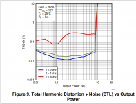
The attached datasheet shows the amp will put out plenty of power (7 or 8 watts RMS) with a 12V power supply and 8 ohm speaker. That should be loud enough to annoy all the adults near your niece. 😀
Better yet, it is well within the ratings that Texas Instruments specifies for the chip even when used without a heatsink, on a single-layer PCB. That means it probably won't overheat, unless you're experiencing a 45 degree C day. 😱
Thanks, that helps a lot! I will look at those when I get a chance. No time right now.Also, links to the parts I am using.
That is still backwards. For an attenuator between preamp and power amp, you want the attenuator to have a HIGH input impedance compared to the output impedance of the preamp. You want the attenuator to have a LOW output impedance compared to the input impedance of the power amp.Edit: actually I didn't get them backwards this time, as I was talking about the ins and outs of the attenuator, which would have been low in and high out to match the high out and low in of the pre!
-Gnobuddy
Attachments
Highest priorities, already discussed, but still not addressed, as far as I know:
1) Ground the amp to the mains. It is unsafe until you do this. It will hum until you do this. Please don't put this off!
2) Remove that volume control from the input. The thing is utterly useless as a guitar amplifier until this is done.
3) Add a volume control to the preamp output. This will let you manage the loudness while still developing the circuit to get the gain you need (seems to be insufficient at the moment, based on clean tones only.)
4) Lower the power supply voltage until the amp stops cutting out. Cutting out is a near-death experience for the amp - the TPA3118 datasheet says the chip reaches 150 degrees Celsius before it shuts down. This is hot enough to do damage, and will reduce the life of the chip.
I'm leery of the idea of using an external buck-boost regulator to lower the power supply voltage. How do we know if it's the regulator that's overheating and shutting down, or the power amp?
Also, three switching devices in close proximity (switching voltage regulator, switching power supply, switching class D amp) can potentially interact and cause squeals and other nasty noises in the speaker.
If you have a 12V DC or similar switching power supply lying around the house, why not try that?
5) Add shielding - grounded baking pan, etc.
It will indeed make the power amp clip earlier (at a lower power level.) But this assumes the power amp is working in the first place - yours isn't, since it's repeatedly overheating and shutting down. Poor little overcooked amp. 😱
The Hippocratic Oath for power amps is the same as for doctors - first do no harm. Be kind to it, turn down the power supply voltage so the amp works properly! 🙂
Also, your amp is already too loud, so reducing the power output is not an issue yet - it only becomes an issue if power is lowered so much that the the power amp starts clipping while the amp is still not loud enough for you (or your niece.)
There is recommendation, and there is reality. Reality is that your amp is overheating and shutting down on 18.5 volts. Ergo, reality requires you to lower the power supply voltage considerably from 18.5.
The attached datasheet shows the amp will put out plenty of power (7 or 8 watts RMS) with a 12V power supply and 8 ohm speaker. That should be loud enough to annoy all the adults near your niece. 😀
Better yet, it is well within the ratings that Texas Instruments specifies for the chip even when used without a heatsink, on a single-layer PCB. That means it probably won't overheat, unless you're experiencing a 45 degree C day. 😱
Thanks, that helps a lot! I will look at those when I get a chance. No time right now.
That is still backwards. For an attenuator between preamp and power amp, you want the attenuator to have a HIGH input impedance compared to the output impedance of the preamp. You want the attenuator to have a LOW output impedance compared to the input impedance of the power amp.
-Gnobuddy
Just to be clear, because it seems that you misunderstood me, the power amp only cuts if the pre is turned up too high, or that one time when I didn't ground the pots and must've had 12vac on the output line I think, basically when it's noisy from the pre I have had the amp shut down, the heatsink wasn't that hot though, I think it was the overvolt protection on the input stage shutting down to stop damage, and as soon as it did that I shut down the power to the pre, which resulted in the noise slowly going away as the amp cut less and less over a few seconds until finally the pre had cooled off and the power amp was fine, it runs cold at 18v normally. I have touched the heatsink after about 10 min of playing through it when I had good tests but couldn't turn up the pre too much, and it was still cold. It only ever got warm when I ran 24v direct into the amp, hence the voltage converter. I need to fit the power section inside the box and run it off one power lead and the on off switch basically, so I got smoothers that have a couple of big caps and inductors on them, as I linked to.
Long story short: I am not worried about the power amp running at 18v in normal operation, it will only cut if the input goes overvolt, which of course is a good thing! I will concentrate on keeping the input signal voltage within the amp's parameters before I try lowering the voltage. Sorry I must have said something in a weird way and you took that as the power amp always cuts, this is not the case! Only when the signal in is too high!
As for the rest of the suggestions: I am on it, but at the moment I am drilling and filing holes in the old sub box to put the pots and switches etc in. Bloody annoying because the pots I have are short shaft and the wood is almost thicker than the whole shaft length! So I am currently drilling out some 25mm holes half way through the wood from the back so that they can mount! Once I have everything in the cab with wires coming down to hook up, I will be doing a full re wire and earthing everything etc. Before I power it up again. Also I did a check and apart from the speaker negative on the power amp I get continuity on all earth wires from the jack to the power supply, which has an earth wire inside it going to the plug, so it should be earthed at the 24v psu at least, and it will also be earthed to the case and I will run earths to a junction point there as well for the rest of the stuff.
cheers again! off to work!
Last edited:
Sorry, I'm trying to guess what's going on a lot of the time, trying to interpret the actual explanation for what you report (I'll explain this a little more in a moment, bear with me.)Just to be clear, because it seems that you misunderstood me...
If I were standing next to you at your workbench, we'd have this all sorted out in a jiffy. Sadly, all we've got is slow, confusing, error-filled back and forth via this forum. And the truth is I'm starting to get exhausted - it's starting to feel as though we're going around and around in circles, with zero net progress.
I don't understand "12V AC on the output line" at all. The preamp is being fed 30V DC, not 12V AC. That 12V AC is only going into the voltage doubler. So I can't see any way for 12V AC to show up on the preamp output lines. 😕the power amp only cuts if the pre is turned up too high, or that one time when I didn't ground the pots and must've had 12vac on the output line I think, basically when it's noisy from the pre I have had the amp shut down
This is one example of why I'm guessing / misunderstanding your explanations. I can't see a way for 12V AC to show up on the preamp output, so I have to rule out that as the cause of the problem. So then I have to guess as to what is the source of the problem.
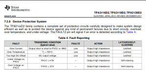
As far as I can tell (see attached datasheet snip), the TPA3118 has no such protection against input signal being too big. It does have protection against too much power supply voltage, too little power supply voltage, too much output current, too high a chip temperature, and too much DC offset between the two speaker outputs. But no protection against being fed too much input signal.I think it was the overvolt protection on the input stage shutting down to stop damage
So why did the TPA3118 shut down, then? My first guess is that it is because it was asked to put out more power than it could handle - there was so much hum and buzz and noise on the input that it was being driven to put out lots of power, enough watts to overheat it, which caused thermal shutdown.
I cannot be 100% sure that my explanation is the correct one. But there is a simple way to find out: lower the power supply voltage to the power amp. If it stops shutting down, you've confirmed that excessive supply voltage is the cause (more on that in a minute.) If it still continues to shut down, we're back to looking for a different cause.
And speaking of a different cause, look at the second attached image, taken from the 'Web ad for your DC-DC converter. It too needs a heatsink to supply its rated maximum 3A output current. (Personally, I wouldn't trust that 3A maximum rating anyway, not without a real datasheet to prove it.)
Your amp, operating on 18.5 volts, will draw 2 amps peak if the speaker is very gentlemanly and behaves like a perfect 8 ohm resistor. Real speakers are unruly, and often draw much more current than an equivalent pure resistance. It's quite likely that your amp is trying to draw peaks of 3 A or more. Therefore the shutdowns you're experiencing might also be caused by the DC-DC converter being overloaded, and not the TPA 3118.
The experiment to find out is similar to the previous one: try running the power amp without the DC-DC converter, which probably means you also have to use a lower-voltage power supply. If the shutdowns stop, well, you've cured your problem, so you don't need either the DC-DC converter, or the higher-voltage power supply.
This might mean the heatsink isn't adequately mounted to the chip. If there is a high thermal resistance between chip and heatsink, the chip underneath will cook, while the heatsink doesn't get very hot....the heatsink wasn't that hot though...
Or it might be that you're right, and it's the DC-DC converter that's cutting out. The easiest way to find out is to eliminate the DC-DC converter.
By the way: if you have a laptop power supply lying around, there is a very good chance it puts out 18.5 V DC (that information will be printed on it somewhere, along with the output polarity.) If so, and if it has the same 5.5mm "barrel plug" on it, you can try running your audio amp off that, rather than the DC-DC converter / step down regulator.
If the amp runs well on the laptop PSU, but not on the DC-DC converter, that points a finger at the likely cause of the problem - not the 18.5V power supply voltage, but rather, the DC-DC converter.
-Gnobuddy
Attachments
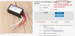
I just looked up your 12 V power supply link, and found another major problem. What you have is not a transformer at all - it's a high-frequency switching power supply, and is not at all suitable for powering your preamp. (It's fine for powering a 12V halogen bulb, which doesn't care about hum and noise on its power.)
The old-fashioned iron-core, 60 Hz AC transformer is what your preamp was designed to work on. But those are thin on the ground these days. High-frequency switching supplies like the one you bought are smaller, lighter, cheaper, use less precious iron and copper, so they've taken over the market for halogen transformers. But they're noisy as all @#!*?, switch too fast for the rectifier diodes on your preamp board to handle, and may be unsafe, as the secondary is floating and not grounded. In short, DO NOT use this to power your valve preamp. 😱
Find a proper 60 Hz (or 50 Hz, in your country), 240V: 12V AC step down transformer. I think that will solve many of the buzz / hum / noise problems you've been experiencing.
-Gnobuddy
Attachments
That was also my worry, I have been testing with a spare 12v wall block, and it's heavy as hell so I think it's basically just a transformer in a box, I will not use those psu's! I'll save them for when the halogen lights in the kitchen take a crap I guess! XDI just looked up your 12 V power supply link, and found another major problem. What you have is not a transformer at all - it's a high-frequency switching power supply, and is not at all suitable for powering your preamp. (It's fine for powering a 12V halogen bulb, which doesn't care about hum and noise on its power.)
The old-fashioned iron-core, 60 Hz AC transformer is what your preamp was designed to work on. But those are thin on the ground these days. High-frequency switching supplies like the one you bought are smaller, lighter, cheaper, use less precious iron and copper, so they've taken over the market for halogen transformers. But they're noisy as all @#!*?, switch too fast for the rectifier diodes on your preamp board to handle, and may be unsafe, as the secondary is floating and not grounded. In short, DO NOT use this to power your valve preamp. 😱
Find a proper 60 Hz (or 50 Hz, in your country), 240V: 12V AC step down transformer. I think that will solve many of the buzz / hum / noise problems you've been experiencing.
-Gnobuddy
Last edited:
I will take all of this under advisement, thankyou for taking the time to help me! I think with the information that is in the 6 pages or so of this post, I will be able to nut out any more problems and next post should be photos of a working amp, though that might be a few more days.Sorry, I'm trying to guess what's going on a lot of the time, trying to interpret the actual explanation for what you report (I'll explain this a little more in a moment, bear with me.)
If I were standing next to you at your workbench, we'd have this all sorted out in a jiffy. Sadly, all we've got is slow, confusing, error-filled back and forth via this forum. And the truth is I'm starting to get exhausted - it's starting to feel as though we're going around and around in circles, with zero net progress.
I don't understand "12V AC on the output line" at all. The preamp is being fed 30V DC, not 12V AC. That 12V AC is only going into the voltage doubler. So I can't see any way for 12V AC to show up on the preamp output lines. 😕
This is one example of why I'm guessing / misunderstanding your explanations. I can't see a way for 12V AC to show up on the preamp output, so I have to rule out that as the cause of the problem. So then I have to guess as to what is the source of the problem.
As far as I can tell (see attached datasheet snip), the TPA3118 has no such protection against input signal being too big. It does have protection against too much power supply voltage, too little power supply voltage, too much output current, too high a chip temperature, and too much DC offset between the two speaker outputs. But no protection against being fed too much input signal.
So why did the TPA3118 shut down, then? My first guess is that it is because it was asked to put out more power than it could handle - there was so much hum and buzz and noise on the input that it was being driven to put out lots of power, enough watts to overheat it, which caused thermal shutdown.
I cannot be 100% sure that my explanation is the correct one. But there is a simple way to find out: lower the power supply voltage to the power amp. If it stops shutting down, you've confirmed that excessive supply voltage is the cause (more on that in a minute.) If it still continues to shut down, we're back to looking for a different cause.
And speaking of a different cause, look at the second attached image, taken from the 'Web ad for your DC-DC converter. It too needs a heatsink to supply its rated maximum 3A output current. (Personally, I wouldn't trust that 3A maximum rating anyway, not without a real datasheet to prove it.)
Your amp, operating on 18.5 volts, will draw 2 amps peak if the speaker is very gentlemanly and behaves like a perfect 8 ohm resistor. Real speakers are unruly, and often draw much more current than an equivalent pure resistance. It's quite likely that your amp is trying to draw peaks of 3 A or more. Therefore the shutdowns you're experiencing might also be caused by the DC-DC converter being overloaded, and not the TPA 3118.
The experiment to find out is similar to the previous one: try running the power amp without the DC-DC converter, which probably means you also have to use a lower-voltage power supply. If the shutdowns stop, well, you've cured your problem, so you don't need either the DC-DC converter, or the higher-voltage power supply.
This might mean the heatsink isn't adequately mounted to the chip. If there is a high thermal resistance between chip and heatsink, the chip underneath will cook, while the heatsink doesn't get very hot.
Or it might be that you're right, and it's the DC-DC converter that's cutting out. The easiest way to find out is to eliminate the DC-DC converter.
By the way: if you have a laptop power supply lying around, there is a very good chance it puts out 18.5 V DC (that information will be printed on it somewhere, along with the output polarity.) If so, and if it has the same 5.5mm "barrel plug" on it, you can try running your audio amp off that, rather than the DC-DC converter / step down regulator.
If the amp runs well on the laptop PSU, but not on the DC-DC converter, that points a finger at the likely cause of the problem - not the 18.5V power supply voltage, but rather, the DC-DC converter.
-Gnobuddy
Update for you:
I took the tube sockets and LED's out of the pre and moved them to wire links, mounted new (red not blue) LED's inside the hole of the tube holder, drilled holes in the top of the speaker cab and glued on 2 rubber grommets, so I can now just push the tubes up into the grommets and they light up red and glow red as well! This should also solve any microphonics for now since they will be essentially shock mounted, I will test the 10 extra tubes I get and give her the least microphonic ones later on.
I have built the tone stack onto the back of 2 pots, there are holes in the top of the cab for the tone knobs, volume, power, a 3 position switch that will either mute, provide a 15db pad on the input for using the POD, or full signal to the tubes for cranked tube overdrive if she so wishes (hopefully, still nutting out how much sig to attenuate etc but experiments should prove fruitful) I have mounted the breaker in the back ready to wire up, the input jack is in but has to be wired, I pretty much spent today drilling holes and cleaning up the wood work on the top ready for mounting so I can get it all in there and do some proper testing! That's tomorrow's job though, I gotta go out tonight. I reckon I am only a couple of days away from a working amp though!
Thank you again!
Photos next post!
- Status
- Not open for further replies.
- Home
- Live Sound
- Instruments and Amps
- Questions on a hobbled together amplifier I am trying my hand at.