The issue of multiple windings to use them for negative feedback is the Leakage Reactance and the Distributed Capacitance of the windings.
The plate winding and negative feedback winding may not be accurately in phase (or may not accurately be out of phase).
It can even be an issue for Ultra Linear primaries. If the leakage reactance is high, from the UL portion of the primary to the rest of the primary winding (to the plate), then there can be a delay from the plate action to the UL screen. That means the phase of the UL negative feedback is not accurate.
How about that?
 hehe
heheI can see that there are good reasons why it may/may not give an identical signal, and why something that at first glance looks like a brilliant idea, may not be so bright.
Thank you. I guess the proof is in the pudding, and as usual the OPT plays a pivotal part.
This is especially helpful to me since I don't have a scope or any other sophisticated measurement devices. Thanks.As stated, not all OPT's have the same phasing, so you must try CFB one way, then reverse the secondary and try again. Choose the connection that gives the lowest gain (volume level for a given volume pot setting) to ensure negative (not positive) feedback.
When testing for phasing in this manner I have seen an EL34 actually oscillate when the phasing was wrong with some OPT's. The amp will make a loud squeal or hum. Reverse the wires and try again if this happens.
Any testing on a brand new amp should be done with junk speakers. I use a pair of Cerwin Vega's that I got at a Goodwill in Florida for $10. Won't cry if I blow them up, but they're still alive after 2 years of abuse.
Any testing on a brand new amp should be done with junk speakers. I use a pair of Cerwin Vega's that I got at a Goodwill in Florida for $10. Won't cry if I blow them up, but they're still alive after 2 years of abuse.
That's more like it.And without those useless diodes.
Mona
I meant to ask earlier but what is the function of the 4.7k resistor in the schematic posted by Ketje?I was looking at the schematic. In post 1 and thinking, "there should be a resistor in there" and then seeing Ketje's schematic in post 3 reassured me that I'm not crazy after all (much).
It's in parallel with the resistance of the OT secondary.
Since the resistance in the secondary is ~.4 ohms the resistance with the 4.7k in parallel is .39997 ohms. So what's the point of having the 4.7k in there?
What am I missing?
Attachments
Last edited:
Only for a swith with "centre off" to have three possible modes of feedback.I meant to ask earlier but what is the function of the 4.7k resistor in the schematic posted by Ketje?
It's in parallel with the resistance of the OT secondary.
Since the resistance in the secondary is ~.4 ohms the resistance with the 4.7k in parallel is .39997 ohms. So what's the point of having the 4.7k in there?
What am I missing?
The resistor keeps the cathode capacitor charged to prevent a plop while switching.
Mona
Thanks.Only for a swith with "centre off" to have three possible modes of feedback.
The resistor keeps the cathode capacitor charged to prevent a plop while switching.
Mona
I'm undecided about adding a switch but, if I do, it will probably be a simple on/off between the cathode and and the positive side of the cap. So the choice would be between Local NFB and an unbypassed cathode resistor (degenerative negative feedback).
In that situation the 4.7k wouldn't be necessary, correct?
I would insert a resistor in a different place, I didn't look at the drawing closely enough.
How I have accomplished a similar thing, whether it is correct or not...well...its not for me to say haha.
I take the cathode resistor (and bypass capacitor, if used, as parallel pair). I insert another resistor between that and ground. I inject the FB into the node between the two resistors.
I thought Ketje's drawing showed that, but it does not, due to the separate ground reference symbols.
Fla Charlie,
If you switch the bypass cap in and out, you will get a "PoP!"
Just as Mona essentially said:
Changing the charge on a cathode bypass cap will cause a transient current to/from the cathode.
I think her switch and resistor is genius.
Simple, and Works Great!
Even if you arrange it as the way you said in post # 26, you need to keep the cap at a constant voltage.
And that brings up a similar system.
You have a Pentode / Ultra Linear switch.
Never change the position of that switch when the amp is on; Or expect a loud "Pop" in your speakers.
You will also be "testing" the breakdown voltage of the OPT and of the tube.
The same goes for a Triode Wired / Ultra Linear switch that I have on one of my amps.
The only way I will change the position of that switch is when the amp is off (no B+, or no warm cathode, or both, whichever happens first).
I did do an experiment, I shorted the OPT secondary, and switched from T to UL, or from UL to T modes.
(But the transient voltage on the plate will still be there, only shortened in time).
The reason is that with the screen falling to Zero volts during switching time, the plate current also falls to Zero. With the OPT current instantly falling from Quiescent to Zero, the primary voltage will spike to very high voltages.
Ever heard of an Induction Coil on a car that raises 12V to 10s of thousands of volts?
But the leakage reactance from the primary to the shorted secondary is the only thing that reduces the time of the transient plate voltage and transient primary voltage.
Your Mileage may vary (and so may your OPT).
Last edited:
I'm confused. Suppose the cap is not connected to the cathode while the amp is playing with only the unbypassed cathode resistor. How is the cap being charged? Or will it only become charged after it has been connected to the cathode? (With the amp powered up, of course)If you switch the bypass cap in and out, you will get a "PoP!"
Just as Mona essentially said:
Changing the charge on a cathode bypass cap will cause a transient current to/from the cathode.
I think her switch and resistor is genius.
Simple, and Works Great!
Even if you arrange it as the way you said in post # 26, you need to keep the cap at a constant voltage.
And that brings up a similar system.
You have a Pentode / Ultra Linear switch.
And, if it was charged previously (by being connected to the cathode) and then it was switched out of the circuit, how long would it retain the charge?
Wouldn't any residual charge slowly (or perhaps quickly) bleed off through the 0.39997 ohm resistance that results from having the 4.7k and the 0.4 ohm secondary in parallel? Or will it hold a charge indefinitely if the positive lead is left disconnected?
The original schematic that I found online, which Mona modified, shows an UL tap but my OT is not UL. So there won't be any Pentode - Triode - UL switch. The amp will operate in Pentode only.
FlaCharlie,
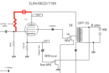
1. You can incorporate a Pentode / Triode Wired switch if you want to (use a 100 Ohm screen resistor).
The switch connects the 100 Ohm screen resistor to B+ (Pentode mode), or to the plate (Triode wired mode).
Again, only change the switch position when the amp is really off.
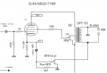
2. If you look closely at Mona's schematic, the top of the bypass cap is always connected to the cathode. The 4.7k resistor will keep the cap charged when the switch is Between position 1 and position 2.
When the bottom of the cap is connected to the secondary, than the very low impedance is in parallel with the 4.7k (therefore the 4.7k does not take any significant power from the 8 Ohm secondary).
When the bottom of the cap is connected to ground, the 4.7k is shorted out by the switch (no problem).
Yes, it is a little hard to see, I hope I have explained it well.
The cathode either sees 1000uF to direct to ground, or it sees 1000uf through the secondary to ground.
(Or, when the switch is mid-position, the 4.7k keeps the cap charged (so little or no "Pop").
1. You can incorporate a Pentode / Triode Wired switch if you want to (use a 100 Ohm screen resistor).
The switch connects the 100 Ohm screen resistor to B+ (Pentode mode), or to the plate (Triode wired mode).
Again, only change the switch position when the amp is really off.
2. If you look closely at Mona's schematic, the top of the bypass cap is always connected to the cathode. The 4.7k resistor will keep the cap charged when the switch is Between position 1 and position 2.
When the bottom of the cap is connected to the secondary, than the very low impedance is in parallel with the 4.7k (therefore the 4.7k does not take any significant power from the 8 Ohm secondary).
When the bottom of the cap is connected to ground, the 4.7k is shorted out by the switch (no problem).
Yes, it is a little hard to see, I hope I have explained it well.
The cathode either sees 1000uF to direct to ground, or it sees 1000uf through the secondary to ground.
(Or, when the switch is mid-position, the 4.7k keeps the cap charged (so little or no "Pop").
Last edited:
"Optimized Electron Stream Technology?"
i remember it was smoking-amp who read the webpage and then called it "blah,blah,blah...." can't disagree with him..
i would rather put my money on Langford and Smith....RDH4...
or Norman Crowhurst....
The issue of multiple windings to use them for negative feedback is the Leakage Reactance and the Distributed Capacitance of the windings.
The plate winding and negative feedback winding may not be accurately in phase (or may not accurately be out of phase).
It can even be an issue for Ultra Linear primaries. If the leakage reactance is high, from the UL portion of the primary to the rest of the primary winding (to the plate), then there can be a delay from the plate action to the UL screen. That means the phase of the UL negative feedback is not accurate.
How about that?
The issue of the feedback signal not being exactly in phase with the main signal is normal. Only at very low frequencies it is in phase, and the phase shift will increase with frequency. Again, that happens in ALL feedback amps.
It becomes a problem if the phase shift approaches 180 degrees while the gain is still above 1, because at that point it becomes positive feedback causing instability.
It is the task of the designer to take care that this doesn't happen. It is very rarely an issue, and when it is, most times points to a design oversight.
Other than that, it isn't an issue.
BTW This phase shift doesn't cause delay, the feedback signal still at all times changes in sync with the main signal, but the phase is (obviously) different.
Jan
BTW I still try to understand why this thread is called 'local feedback'. It is a textbook example of global feedback. All the way from the speaker back to the input.
Jan
Jan
sgNFB (short..) 🙂
A cap from plate, then a resistor to g1 for local feedback.
But probably less effective?
A cap from plate, then a resistor to g1 for local feedback.
But probably less effective?
I think it would be helpful for me to restate the information about this project that I wrote in the first post:FlaCharlie,
1. You can incorporate a Pentode / Triode Wired switch if you want to (use a 100 Ohm screen resistor).
The switch connects the 100 Ohm screen resistor to B+ (Pentode mode), or to the plate (Triode wired mode).
Again, only change the switch position when the amp is really off.
2. If you look closely at Mona's schematic, the top of the bypass cap is always connected to the cathode. The 4.7k resistor will keep the cap charged when the switch is Between position 1 and position 2.
When the bottom of the cap is connected to the secondary, than the very low impedance is in parallel with the 4.7k (therefore the 4.7k does not take any significant power from the 8 Ohm secondary).
When the bottom of the cap is connected to ground, the 4.7k is shorted out by the switch (no problem).
Yes, it is a little hard to see, I hope I have explained it well.
The cathode either sees 1000uF to direct to ground, or it sees 1000uf through the secondary to ground.
(Or, when the switch is mid-position, the 4.7k keeps the cap charged (so little or no "Pop").
If the switch is used to connect the cap directly to ground, thereby bypassing the cathode resistor, there will be no NFB. My understanding is that operating a pentode without any NFB is not considered such a good move sonically. Therefore some form of NFB is in order.I have a SE VM that originally had the preamp section connected with an umbilical. The amp section only has a 5Y3 and a pair of 6BQ5s. I want to drive it with either a stand-alone tube pre I built or a SS pre. So I won't be using global NFB like the one that went to the stock preamp through the umbilical.
My amp does NOT have an UL tap like the one in the schematic. I want to get as much power out of it as I can so I want to stick with pentode instead of converting it to triode.
So it's either pentode with no FB or some type of local FB. Are there other local FB methods that I should consider?
So it will definitely use the Local NFB scheme shown which connects the 1000uf cap through the secondary to ground.
The other option I'm considering is to install a switch that would remove the Local NFB through the OT secondary and use an unbypassed cathode resistor which, as I understand it, would result in a lesser amount of feedback (aka degenerative feedback) than the cap to secondary connection.
In order to remove the cap from the circuit it must either be disconnected from the cathode on the + side or disconnected from the OT secondary on the - side.
So, where should the switch be installed? Or does it matter?
Is there a way to install it so that it can be switched, while the amp is on, without creating a "pop"? Or must it only be switched before the amp is powered up?
Last edited:
The instability / phase issue has been dealt with by reversing the wires on the OT secondary, as recommended in an earlier post.The issue of the feedback signal not being exactly in phase with the main signal is normal. Only at very low frequencies it is in phase, and the phase shift will increase with frequency. Again, that happens in ALL feedback amps.
It becomes a problem if the phase shift approaches 180 degrees while the gain is still above 1, because at that point it becomes positive feedback causing instability.
My understanding is that the term "global" refers to feedback that involves more than one stage. Typically, it is connected from the speaker back to the input tube.BTW I still try to understand why this thread is called 'local feedback'. It is a textbook example of global feedback. All the way from the speaker back to the input.
In this case there is no input tube installed on the chassis. There is only one stage, an output stage. Separate preamps will be used, both tube and SS, so there is no way to send feedback from the speaker to the input (preamp).
"sg"? I assume the "s" must stand for short and the "g" for global. But it seems local to me if only a single stage is present.sgNFB (short..) 🙂
A cap from plate, then a resistor to g1 for local feedback.
But probably less effective?
I don't recall ever seeing this method but, as I said in my initial post, I'm open to considering other methods.
Are you saying it's just a cap and resistor, in series, between the plate and g1? What values would be appropriate? And why would it be less effective?
Please elaborate. A schematic would be helpful.
Last edited:
My understanding is that the term "global" refers to feedback that involves more than one stage. Typically, it is connected from the speaker back to the input tube.
Well you can quibble about that, this is one tube + transformer. You can do local feedback over the tube only, or global feedback, as is done here, from output to input.
I don't think the # of stages figures in it, that would be a change to the accepted definition that's already almost a century old ;-)
At any rate, it is definitely NOT local feedback, and the only remaining taste we have is global. Unless you want to stray into exotic stuff like nested fb, which it ain't either.
Jan
I struggle regarding feedback so I can't help that much, but here is the principle. Capacitor DC blocker then a resistor to form a divider network with the existing Rg (480K).
From what I've read here and there, a local feedback won't be very effective for noise/hum issues. But we are supposed to build a clean and quiet amplifier *before* applying feedback anyway.
From what I've read here and there, a local feedback won't be very effective for noise/hum issues. But we are supposed to build a clean and quiet amplifier *before* applying feedback anyway.
Attachments
- Home
- Amplifiers
- Tubes / Valves
- Questions About This Local NFB Scheme