I am trying to design a simple ‘open-loop’ output stage with a CCS loaded source follower. I know it looks simple on paper, but there are some things I am not sure about, so I would like to ask some basic questions…
1. What causes distortion in a source follower, and how to minimize it?
2. Apart from Vds, Id, W, and input capacitance, what parameters are most important when choosing a device for a follower, and why are they important?
3. When using tubes I learned that equally spaced parallel lines on the device I / V characteristic graph are ‘a good thing’. Should I presume that the same applies with FETs? [Because most seem to have poor / unequal spacing!]
Thanks Andrew, I will certainly be investigating the articles published by Nelson Pass as you say.
In the mean-time does anyone have any thoughts on any of my questions? (Even if just on one of the questions?)
In the mean-time does anyone have any thoughts on any of my questions? (Even if just on one of the questions?)
Source Follower Distortion
In a source follower, Vout=Vin-Vgs(Ids). As you deliver current into a load, Iout changes. Vgs depends upon Ids, and changes in Ids give useful output current, Iout, and so Ids also changes. So, to minimize distortion:
1. Minimize Iout variation by either:
a) lightly load the source follower
b) give it a high quiescent current, so that the load current variation is relatively small
2. Choose a device with high transconductance for a given current
3. Measure the load current and modulate the previously CCS to make Ids constant, even though you deliver useful load current. (a bit illegal given the no feedback dictum).
4. add feedback around the stage (ok...not allowed, given no feedback).
djoffe, that's just the sort of thing I was hoping for, many thanks for the direction.
Points 1 and 2 noted for imminent use.
I think your point 3 is beyond me.
With reference to point 4, do you mean that it is possbile to have useful local feedback just around a single stage follower, or perhaps to the preceding stage without full-blown global feedback? (Or maybe I have misunderstood you?). If it is possible I would very much like to persue any references / links that you might be able to post?
Thank you.
Last edited:
Local Feedback?
Sure...there are many forms it can take...at some point, it would look a bit too much like an op-amp for some people, but there are some in between things which might be done. I'll try to post some simplified schematics in the next day or so...
Sure...there are many forms it can take...at some point, it would look a bit too much like an op-amp for some people, but there are some in between things which might be done. I'll try to post some simplified schematics in the next day or so...
Emitter Followers
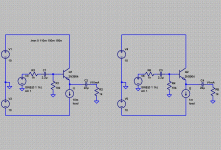
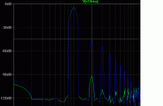
Just because it was easy to simulate, I did emitter followers...two cases, one with 10 mA, and the second with 1 mA. Now, I forced things for drama, but with the 1 volt peak input, the 10 mA circuit is wonderful...the 1 mA circuit is marginal, see enclosed FFTs.
Just because it was easy to simulate, I did emitter followers...two cases, one with 10 mA, and the second with 1 mA. Now, I forced things for drama, but with the 1 volt peak input, the 10 mA circuit is wonderful...the 1 mA circuit is marginal, see enclosed FFTs.
Attachments
Yes, I see it clearly, that illustrates well your point about keeping a favourable ratio between quiescent and output current.
(It's 4:30 am here, so I must leave for now. Thank you again).
(It's 4:30 am here, so I must leave for now. Thank you again).
Hi DJ,
1Vpk input is going to produce ~1Vpk at the output.
Into a 1k load that requires ~1mA of output current.
A single ended device biased to 1mA is on the threshold of overloading (current clipping) at that level.
That is not a fair comparison.
Try increasing the bias to 1.2mA and 1.5mA and 2mA and see what the FFTs look like.
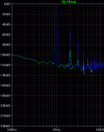
A more moderate case...
Andrew,
You are correct...the case I picked was a corner case...very near clipping...on purpose for drama, but perhaps a bit unfair...enclosed FFT changes the 1.0 mA current source to 1.5 mA, leaving about 0.5 mA thru the transistor...still, there is a great improvement in distortion from using 10 mA, as the new fft shows.
Attachments
I would request that you don't cheat to prove a point..very near clipping...on purpose for drama, but perhaps a bit unfair...
Would be better had you said why you chose 1Vpk and let us see why you don't want to approach current or voltage clipping in a stage.
I have repeatedly said each stage MUST have an overhead of >10dB to feed the next stage and preferably 20dB of overhead.
A well respected expert replied with the equivalent of "don't be a fool, +20dB of overhead is ridiculous".
Guys, thanks for the valuable contributions.
(djoffe, I don't regard you as cheating, just exagerating to prove a point).
Going back to my question:
Most FETs seem to have inconsistent spacing of the lines on the Typical Output Characteristics graph. Do I presume that more equal spacing is better for low distortion? (For example the 2SK1056 [/ 57, 58] seems to have lines equally spaced between 2A and 7A, and is touted as a component applicable for audio amplification).
(djoffe, I don't regard you as cheating, just exagerating to prove a point).
Going back to my question:
When using tubes I learned that equally spaced parallel lines on the device I / V characteristic graph are ‘a good thing’. Should I presume that the same applies with FETs? [Because most seem to have poor / unequal spacing!]
Most FETs seem to have inconsistent spacing of the lines on the Typical Output Characteristics graph. Do I presume that more equal spacing is better for low distortion? (For example the 2SK1056 [/ 57, 58] seems to have lines equally spaced between 2A and 7A, and is touted as a component applicable for audio amplification).
please attach a picture of the curves
Gordy...
That's the best way to make sure my answer is really responsive to your question.
Thanks....
Dan
Gordy...
That's the best way to make sure my answer is really responsive to your question.
Thanks....
Dan
(With hindsight that would have been the sensible thing to do. Apologies for my slowness. I don’t know how to cut out graphs so I have attempted to attach two datasheets).
My previous post was incorrectly worded. What I meant to reference was the Vgs increments on the Typical Output Characteristics graph, which is on page 4 of the 2SK1056 datasheet. From 2 to 7V the horizontal lines are relatively equally spaced in vertical increments.
In contrast the same characteristic graph (Figure 5, page 4) on the IRF820 datasheet illustrates lines progressively increasing in vertical distance as Vgs increases.
When learning about tubes, which are often run without corrective *global* feedback, I learned that equal line increments can produce a lower distortion output, and wondered if it is the same for FETs... so...
Do the more equally spaced lines help even when used within a feedback corrected circuit?
Are they preferable for a source follower, or less important?
Attachments
Last edited:
Equal Spaced is More Linear
Gordy,
Equally spaced lines will produce less distortion than non-equally spaced lines.
If the lines were perfectly equally spaced, you'd have something like this:
Ids=(Vgs-Vth)*k1. You can show that given a constant load resistance, this produces a perfectly linear follower output, though at a slight loss in gain. I've sketched a derivation, but won't bother to clean it up for posting unless there is a demand and I have time.
The nonequal spacing implies something like:
Ids=(Vgs-Vth)^2*k2, which you can show produces a non-linear output.
Dan
Dan, thank you, I'm beginning to understand more.
I'm mindful that this type of thread can soon grow too one-sided, however I hope that you will entertain one further question...
What FET would you recommend for a follower to drive 2W into 8R (4V RMS at 0.7A peak)? Ideally with input capacitance no higher than 600 pF, zero temperature coefficient at a convenient Id / Vgs, and a TO-220 or similar package (non TO-3) for easy fixing. (I assume that Enhancement or Depletion would be OK as long as Rds on is reasonably low). My goal at this stage is best objective performance, and I'm not too concerned about cost within reason as I'm only going to build a stereo pair.
And if you have any other tips and guidelines for choosing this type of part... I'm all ears!
Thanks again,
G.
what is the 8ohm? A speaker, a headphone or a resistor.What FET would you recommend for a follower to drive 2W into 8R (4V RMS at 0.7A peak)?
Your 0.7Apk applies to a resistor load only.
For a headphone or full range driver I would double the current capability.
For a cross-overed speaker I would triple the current capability. That, at a first guess, would require a >=4A Id FET.
A Good Fet?
Except for the package (T03P vs. your desired T0-220), The 2SK1056 you point out would be a good choice. In a follower configuration, the input Capacitance will be much less than the listed 600 pF, perhaps about 1/10 of 600 pF, or 60 pF, assuming an 8 Ohm load and Ids=3 Amps.
The zero tempco thing shouldn't really matter...you will be setting the quiescent current with a current source if you are going class A. Vgs vs T will be a bit squishy, which translates to output offset voltage changing with temp...figure (very roughly) on a few mV/C.
Finally, I haven't done a search for FETs that are nice in the way that you are looking for, equally spaced characteristic curves...I'm sure there are folks on the forum who might have great recommendations.
Dan
How about the IRF510? A TO-220 device with 180 pf Ciss. You could parallel a 3 if you need the extra current capability and stay under 600 pf.
Notice that the higher temperature curves are more evenly spaced than the 25C curves. Wow! Nelson Pass may have been on to something when he said mosfets like to run hot.. 😉
Notice that the higher temperature curves are more evenly spaced than the 25C curves. Wow! Nelson Pass may have been on to something when he said mosfets like to run hot.. 😉
- Status
- Not open for further replies.
- Home
- Amplifiers
- Solid State
- Questions about the humble follower


