I'm considering building a speaker with TAD 4001 or 4003 horn.
I see many are adding another tweeter and crossing the TAD quite low. What's the reason for this?
Also; What is considered to be the best lenses today and where are they sold?
I see many are adding another tweeter and crossing the TAD quite low. What's the reason for this?
Also; What is considered to be the best lenses today and where are they sold?
Hi ,
Tad Be diaphragm with is the most superior diaphragm in terms of weight to strength ratio , tensile strength , Yield strength (mpa) , Youngs modulus . This results in a negligible break up mode distortion characteristics .
The Tad flux density is 2 T by use of D 160 mm d 104 mm Neo Magnets (one of the largest Neo magnets used in compression diaphragms)
Further the impulse behavior to noise floor , residual ringing is best in class , for eg the residue noise after signal burst for Ti diaphragm is about 45 seconds , for Be diaphragm about 8 seconds .
In the critical range of mids where the ear is most susceptible to pick up distortion from residue ringing Be is most suitable for reproducing mids . Further lower distortion reduces listening fatigue .
Therefore Tad drivers are crossed over lower , specially where the maximum rated power levels are (divided) or not fed to the driver , it can be crossed lower than the recommended cross over point .
Once Tads are used for Mid + Mid HI , the upper Hi s are crossed over to Radian 950 pbs or so . Jbl 2440 , 2441 for upper Hi may be considered .
With reference to acoustic lenses to be fitted at the mouth of horns , they may not be available off the shelf .
Suranjan
Thanks for the reply.
Do you have measurements that confirm this?
I can see the reason here in reducing distortion, but at the same time one is increasing lobing by adding another driver. So though it may be a step forward in one area, it's also a step back in another.
Do you have measurements that confirm this?
I can see the reason here in reducing distortion, but at the same time one is increasing lobing by adding another driver. So though it may be a step forward in one area, it's also a step back in another.
Hi there
I am using 4001's in JMLC iwata horns by auto tech (measurements in the link below) crossed to 2001 in 1kHz horns at 2.5kHz 6dB/oct. They are crossed at 550Hz 24dB/oct to a bass reflex.
Frankly speaking I am liking this set-up to fostex tweeters. My 2C
http://www.diyaudio.com/forums/group-buys/166312-waveguides-horns-109.html#post2992305
Be to Ti
Hi
With reference to Be vs Ti Table , please find
3.1 Density
The density of a material, ρ, is defined as the mass per unit volume or ρ = m/V, where m = mass
and V = volume. For a given transducer geometry, a lower-mass diaphragm allows greater
acceleration of the moving system (F=ma), increasing both passband efficiency and highfrequency
extension (Kinsler & Frey; Eargle).
3.2 Young’s Modulus
This is the ratio of uniaxial stress to strain and is measured in units of pressure. It is defined as E
= σ/ε, where σ = stress and ε = strain. A higher Young’s Modulus equates to a stiffer
diaphragm, all other things being equal. A stiffer diaphragm, of course, does not bend as much in
response to an applied force. Thus, at high frequencies, the bending modes are shifted up in
frequency, extending the useful bandwidth of the transducer (see further discussion below).
3.3 Poisson’s Ratio
When a solid material is compressed in one direction, it tends to expand in the other two
directions perpendicular to the direction of compression. This phenomenon is called the
Poisson Effect. The Poisson’s Ratio ν (nu) relates the contraction or transverse strain
(perpendicular to the applied load), to the extension or axial strain (in the direction of the
applied load). Assuming that the material is stretched or compressed along the axial direction:
ν = - dεtransverse / dεaxial
Where
ν is the resulting Poisson's Ratio,
εtransverse is transverse strain (negative for axial tension, positive for axial compression)
εaxial is axial strain (positive for axial tension, negative for axial compression).
The Poisson’s Ratio of beryllium is unusually low. For acoustic applications, a low Poisson’s
Ratio results in reduced coupling of sound waves from one mode of propagation to another.
For example, an axial wave will remain an axial wave transferring less energy to transverse
modes of wave propagation. This ability to keep the different modes of propagation separated
can be of great importance in acoustics, especially at higher frequencies, or in imaging or surface
wave devices (Materion Electrofusion). In other words, a lower Poisson’s Ratio better
preserves the direction of the applied force.
3.4 Speed of Sound
The speed of sound is the rate of travel of a sound wave through an elastic medium. The speed
of sound waves in solids is determined by the material's stiffness and density and may be
described by the equation c = E/ρ . This is generally understood to be the speed of a
longitudinal wave along the x-axis of a long bar (where x >> y or z). For the purposes of this
discussion, we are interested in the bending modes of a thin plate (x and y >> z) where the
displacement of the wave is in the z-axis. The bending stiffness causes the bending wave speed
to be different than c. These relationships are detailed below.
3.5 Tensile Strength
Tensile Strength is the property of a material that measures its ability to withstand tensile stress
without failure. A material with a higher tensile strength allows a thinner dome to maintain
equivalent strength, giving a lower moving mass.
3.6 Bending Modulus (relative to aluminum)
This property describes the stiffness of a thin plate in response to bending forces (similar to
Young’s Modulus, but in two dimensions). Of course, the actual bending stiffness of a dome
shape is highly dependent on the details of that geometry. For this discussion, we separate the
material’s inherent bending stiffness from the geometry’s stiffness by assuming the same thin
plate geometry for all materials. For the sake of clarity in the table, these results have been
shown relative to the Bending Modulus of the aluminum plate.
Table 3: Predicted Bending Mode Frequencies
Natural
Freq(kHz) Aluminum Titanium Tin / Aln Beryllium Ben / Aln
1st mode 10.04 9.98 0.99 26.16 2.61
2nd mode 10.44 10.36 0.99 26.64 2.55
3rd mode 10.56 10.46 0.99 26.79 2.54
4th mode 10.62 10.52 0.99 26.90 2.53
5th mode 10.68 10.58 0.99 27.05 2.53
6th mode 10.76 10.66 0.99 27.28 2.54
First, notice that the Finite Element Model confirms the analytical solution above; if geometry is
held constant, beryllium’s bending modes occur at roughly 2.5x higher frequency than those of
the other materials.
Perhaps even more interesting is the acutely non-harmonic relationship of the modes above the
first. Classical plate theory hints at this, but flat plates and membranes do not exhibit such
closely-spaced modes. While beyond the scope of this study, it is certainly worth noting that
the relationship between the natural frequencies is drastically affected by the geometry of the
dome. The modal density above the first bending mode is much higher than that predicted by
classical (flat) plate theory. Essentially, this lends greater importance to the first bending mode
frequency, since adjacent modes set in so quickly and densely above that frequency.
I strongly recommend Tad to take it on from here as they will benefit finally from the sale else the next post will have critical information on Tad drivers , and how to make Tad drivers from my side .
Best Regards
Suranjan
Transducer design engineer
Attachments

@ hunter audio
Thanks for the info 🙂
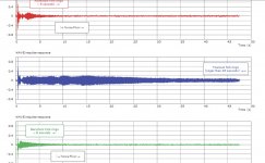
This confirms my dislike for Titanium diaphrams 😀 Even Aluminium looks better on the tuning fork graph 😉
Have you done tests on Phenolic diaphrams, if so could you post similar graphs please. I've heard some nice sounds coming out of one in particular.
I havn't heard the TADS, but would like to sometime 🙂
Thanks for the info 🙂
This confirms my dislike for Titanium diaphrams 😀 Even Aluminium looks better on the tuning fork graph 😉
Have you done tests on Phenolic diaphrams, if so could you post similar graphs please. I've heard some nice sounds coming out of one in particular.
I havn't heard the TADS, but would like to sometime 🙂
Nice
Thanks for taking the time to do an expose on the merits of beryllium as a superior material for use as the diaphragm of an acoustic radiator. Its use in microphones is meritorious as well.
Seldom do I copy, information found here, to my research library. Your submission will be one of the few exceptions, due to its accuracy, completeness, clarity and presentation of term definitions.
Regards,
WHG
Hi
With reference to Be vs Ti Table , please find
3.1 Density
The density of a material, ρ, is defined as the mass per unit volume or ρ = m/V, where m = mass
and V = volume. For a given transducer geometry, a lower-mass diaphragm allows greater
acceleration of the moving system (F=ma), increasing both passband efficiency and highfrequency
extension (Kinsler & Frey; Eargle).
3.2 Young’s Modulus
This is the ratio of uniaxial stress to strain and is measured in units of pressure. It is defined as E
= σ/ε, where σ = stress and ε = strain. A higher Young’s Modulus equates to a stiffer
diaphragm, all other things being equal. A stiffer diaphragm, of course, does not bend as much in
response to an applied force. Thus, at high frequencies, the bending modes are shifted up in
frequency, extending the useful bandwidth of the transducer (see further discussion below).
3.3 Poisson’s Ratio
When a solid material is compressed in one direction, it tends to expand in the other two
directions perpendicular to the direction of compression. This phenomenon is called the
Poisson Effect. The Poisson’s Ratio ν (nu) relates the contraction or transverse strain
(perpendicular to the applied load), to the extension or axial strain (in the direction of the
applied load). Assuming that the material is stretched or compressed along the axial direction:
ν = - dεtransverse / dεaxial
Where
ν is the resulting Poisson's Ratio,
εtransverse is transverse strain (negative for axial tension, positive for axial compression)
εaxial is axial strain (positive for axial tension, negative for axial compression).
The Poisson’s Ratio of beryllium is unusually low. For acoustic applications, a low Poisson’s
Ratio results in reduced coupling of sound waves from one mode of propagation to another.
For example, an axial wave will remain an axial wave transferring less energy to transverse
modes of wave propagation. This ability to keep the different modes of propagation separated
can be of great importance in acoustics, especially at higher frequencies, or in imaging or surface
wave devices (Materion Electrofusion). In other words, a lower Poisson’s Ratio better
preserves the direction of the applied force.
3.4 Speed of Sound
The speed of sound is the rate of travel of a sound wave through an elastic medium. The speed
of sound waves in solids is determined by the material's stiffness and density and may be
described by the equation c = E/ρ . This is generally understood to be the speed of a
longitudinal wave along the x-axis of a long bar (where x >> y or z). For the purposes of this
discussion, we are interested in the bending modes of a thin plate (x and y >> z) where the
displacement of the wave is in the z-axis. The bending stiffness causes the bending wave speed
to be different than c. These relationships are detailed below.
3.5 Tensile Strength
Tensile Strength is the property of a material that measures its ability to withstand tensile stress
without failure. A material with a higher tensile strength allows a thinner dome to maintain
equivalent strength, giving a lower moving mass.
3.6 Bending Modulus (relative to aluminum)
This property describes the stiffness of a thin plate in response to bending forces (similar to
Young’s Modulus, but in two dimensions). Of course, the actual bending stiffness of a dome
shape is highly dependent on the details of that geometry. For this discussion, we separate the
material’s inherent bending stiffness from the geometry’s stiffness by assuming the same thin
plate geometry for all materials. For the sake of clarity in the table, these results have been
shown relative to the Bending Modulus of the aluminum plate.
Table 3: Predicted Bending Mode Frequencies
Natural
Freq(kHz) Aluminum Titanium Tin / Aln Beryllium Ben / Aln
1st mode 10.04 9.98 0.99 26.16 2.61
2nd mode 10.44 10.36 0.99 26.64 2.55
3rd mode 10.56 10.46 0.99 26.79 2.54
4th mode 10.62 10.52 0.99 26.90 2.53
5th mode 10.68 10.58 0.99 27.05 2.53
6th mode 10.76 10.66 0.99 27.28 2.54
First, notice that the Finite Element Model confirms the analytical solution above; if geometry is
held constant, beryllium’s bending modes occur at roughly 2.5x higher frequency than those of
the other materials.
Perhaps even more interesting is the acutely non-harmonic relationship of the modes above the
first. Classical plate theory hints at this, but flat plates and membranes do not exhibit such
closely-spaced modes. While beyond the scope of this study, it is certainly worth noting that
the relationship between the natural frequencies is drastically affected by the geometry of the
dome. The modal density above the first bending mode is much higher than that predicted by
classical (flat) plate theory. Essentially, this lends greater importance to the first bending mode
frequency, since adjacent modes set in so quickly and densely above that frequency.
I strongly recommend Tad to take it on from here as they will benefit finally from the sale else the next post will have critical information on Tad drivers , and how to make Tad drivers from my side .
Best Regards
Suranjan
Transducer design engineer
Thanks for taking the time to do an expose on the merits of beryllium as a superior material for use as the diaphragm of an acoustic radiator. Its use in microphones is meritorious as well.
Seldom do I copy, information found here, to my research library. Your submission will be one of the few exceptions, due to its accuracy, completeness, clarity and presentation of term definitions.
Regards,
WHG
Well, I don't know guys.
We're talking about a driver and horn that already has very low distortion.
It depends on what's audible and how this compares to the disadvantage of a worse polar response.
I would assume the latter is more important then minimizing something that's already very low.
We're talking about a driver and horn that already has very low distortion.
It depends on what's audible and how this compares to the disadvantage of a worse polar response.
I would assume the latter is more important then minimizing something that's already very low.
Thanks , the research is from a premium supplier of be diaphragms , I am in touch with one of the persons behind the tests , Mr. Grodon Simmons .
Suranjan, thanks for posting this information. Very helpful. I am also researching various compression drivers (Radian, TAD, or BMS) to couple with JMLC Iwata-300, 3-way design very similar to Gluca's.
Be Diaphragm Ref.
Here are junst a few:
http://materion.com/~/media/Files/PDFs/Electrofusion/PLS2011PAPERFINAL.pdf
Truextent® BeX? Diaphragm Assembly ? Materion Electrofusion - Materion
http://www.diyaudio.com/forums/multi-way/169937-truextent-beryllium-replacement-diaphragms.html
The Use Of Beryllium In Transducers ? VUE Audiotechnik
Regards,
WHG
Wgh
Be is superior , it does not end there , this is the just a few
1) Phase plugs , Tads is good but not the best
2) The shorting rings are missing ? in all compression drivers , ever wondered why ?
3) The obvious competition from ring radiators due to low moving mass & the d2 format .
They say the leading thought is the main thing , after that a human being will find the goal
well take care guys
Suranjan
1) Phase plugs , Tads is good but not the best
Are you thinking about the Radian there?
I hope John won't mind if I re-post his answer regarding Tad 4001 horn with which I happen to agree.
....The TH-4001 is a hyperbolic horn and sounds peaky as hell. It is unlistenable IMO, even worse than exponential horns. Very colored and it can’t image because of the throat fins. However, if you choke it down, like you said 12dB â€" 15dB, it becomes almost listenable. However, it still can’t throw a realistic image. Because TAD does pad their horns down by 12dB â€" 15dB, the hyperbolic profile is the only one they could use to retain any sort of liveliness to the music. As you already know, when you use resistive L-pads to attenuate a driver it kills the dynamics. It works out great for TAD as a studio monitor, but should not be used in the home environment.....
Rgs, JLH
- Status
- Not open for further replies.
- Home
- Loudspeakers
- Multi-Way
- Questions about TAD horn