1) What is electric current?
Electrons flow or electron drift is very slow, to the order of 2.3 x 10^-5 m/s.
According to the Wikipedia article:
"In physics, a drift velocity is the average velocity attained by charged particles, such as electrons, in a material due to an electric field. In general, an electron in a conductor will propagate randomly at the Fermi velocity, resulting in an average velocity of zero. Applying an electric field adds to this random motion a small net flow in one direction; this is the drift."
Drift velocity - Wikipedia
1 Ampere of current is 1 C /s . How many electrons need to flow past a point per second to generate this current? This depends on how many Coulombs are contained in copper wire and what the charge on each electron is.
Number of electrons per second = 1C / (charge of an electron * number of electrons)
The calculation is given in the article. Is this an oversimplification?
2) What are the electrical characteristics of the output from audio playback devices, and how to can it be safely measured?
In audio amplification, the signal from an audio player: mobile phone, DVD player, tape deck, turntable or preamplifier is what gets amplified. I have connected the output from a computer audio out directly to a small speaker, and and could hear music. In a simple class A amplifier, it is this signal that goes into the base of the transistor, is it less than the current needed to turn on the transistor? Is this why the transistor is 'biased', that is a small current is applied to the transistor to move it into the working range?
In audio amplification, the signal from an audio player: mobile phone, DVD player, tape deck, turntable or preamplifier is what gets amplified. I have connected the output from a computer audio out directly to a small speaker, and and could hear music. In a simple class A amplifier, it is this signal that goes into the base of the transistor, is it less than the current needed to turn on the transistor? Is this why the transistor is 'biased', that is a small current is applied to the transistor to move it into the working range?
2)
In audio amplification, the signal from an audio player: mobile phone, DVD player, tape deck, turntable or preamplifier is what gets amplified. I have connected the output from a computer audio out directly to a small speaker, and and could hear music. In a simple class A amplifier, it is this signal that goes into the base of the transistor, is it less than the current needed to turn on the transistor? Is this why the transistor is 'biased', that is a small current is applied to the transistor to move it into the working range?
You might be confusing voltage and current here.
A signal of for example 100 millivolts peak amplitude may be delivered from a source of high current ability.
What does that mean... it means that lets say you placed a 0.1 ohm load across the 100 millivolts (silly I know but...) then the current flow iwould be 0.1/1 which is 0.1 amps.
That signal is easily audible if applied to a speaker.
If you apply it to an unbiased transistor then it will not cause the transistor to conduct because the transistor needs about 0.6 volts between its base and emitter before any current can flow anywhere.
So as you correctly say, the transistor is pre biased to move the operating point to a more linear part of the transfer curve. When pre biased the small change in signal voltage can linearly shift the operating point by modulating that preset bias we have applied.
As well as needing voltage (signal voltage) we also need current (signal current) for the transistor to work.
Our 100mv peak voltage source if fed for example via a 10 meg resistor is still a 100mv peak source but now we can draw virtually no current. It would be inaudible in a speaker because 99.99% of the voltage is lost across the 10meg.
There would now be insufficient current to operate a transistor even though in basic terms we still have a 100mv source.
Computer, mobile phone and DVD player output voltages
Yes I think I am, and that is what I want to sort out.
In the meantime I have made measurements to the outputs from my laptop, mobile phone and DVD players: (1 kHz sine wave, online tone generator, 50% volume)
Source zero volume to max volume (Multi-meter in AC Voltage mode)
Laptop: 0.00 mV to 100 mV
Mobile Phone: 0.00 mV to 70 mV
DVD Player: 2 Volts to 9 Volts (Multi-meter in AC Voltage mode)
DC mode - a few millivolts.
I can even sense the current in my fingers when I touch the RCA jack running from the DVD player. Is there a short internally? Is this how it works normally? The player plays music fine, though it skips sometimes.
The next step will be to connect the output to a high impedance headphone or speaker and measure current in Amps.
You might be confusing voltage and current here.
Yes I think I am, and that is what I want to sort out.
In the meantime I have made measurements to the outputs from my laptop, mobile phone and DVD players: (1 kHz sine wave, online tone generator, 50% volume)
Source zero volume to max volume (Multi-meter in AC Voltage mode)
Laptop: 0.00 mV to 100 mV
Mobile Phone: 0.00 mV to 70 mV
DVD Player: 2 Volts to 9 Volts (Multi-meter in AC Voltage mode)
DC mode - a few millivolts.
I can even sense the current in my fingers when I touch the RCA jack running from the DVD player. Is there a short internally? Is this how it works normally? The player plays music fine, though it skips sometimes.
The next step will be to connect the output to a high impedance headphone or speaker and measure current in Amps.
Last edited:
How well a DVM works at those low levels is an unknown... some are super accurate and others not. Also you need to be sure 1kHz is within the range of AC frequencies allowable. It probably is but some DVM's might only be good for 50/60 Hz and perhaps up to a few hundred Hertz.
A scope is best 🙂
The high DVD player reading is almost certainly caused by you in some way picking up the voltage that the chassis might be floating to. That is caused by the switching power supply and leakage currents... all normal and safe... but can cause weird results.
I doubt you would record any meaningfull current on a DVM at the low values involved.
100mv (lets assume that is an rms value) across an 8 ohm speaker is just 1.25 milliwatts. The current would be 12.5 milliamps.
If the speaker was higher impedance then the current and power would be even lower.
Those were weird results all right. I found an article on current leakage here:
What is Leakage Current? - Sunpower UK
I am seriously looking at this scope , the built version, not DIY.
https://www.amazon.com/DSO-Shell-Oscilloscope-Enclosure-ESD-Safe/dp/B06Y1T6WZ9
KKmoon 2.4" TFT Digital Oscilloscope Kit with Power Adapter and BNC-Clip Cable Probe DS0150 (Assembled Finished Machine) US Plug
or a sound card based scope for my laptop.
I think it is about time I got a scope.
Output from laptop audio jack. (Headphones connected). Why is it uneven? Do the headphone drivers cause this or is the response not smooth?
50 Hz : 427 mA
100 Hz : 419 mA
1,000 Hz : 424 mA
10,000 Hz: 365 mA
50 Hz : 427 mA
100 Hz : 419 mA
1,000 Hz : 424 mA
10,000 Hz: 365 mA
I think those numbers are very suspect tbh 🙂 That is nearly half an amp.
No laptop/phone/source component would deliver those kind of currents. Something is going wrong with your measurement technique here. No decimal point after the first number perhaps?
To get the feel for it all first listen to your 1kHz tone through a normal amp and speaker at very low volume. Now set the AC voltage across the speaker to just 0.1 volt. It will be quite loud with even that low voltage.
Now put your meter on AC current and insert the meter in series with one of the speaker leads. The level of sound should seem the same and the meter will show current. The exact reading depends on the speaker impedance but it should be in the 10 to 20 milliamp region.
If it is not then something is wrong with the meter and or your measurement set up.
The ability to provide a current.
Current, Voltage and resistance.
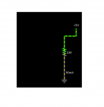
This simple circuit in Falstad sim shows a resistor and a current source. It is confusing to me to talk about voltage. Current consists of the flow of electrons, or charged particles. For example, a charged capacitor connected as the current source will discharge through the resistor. A battery will also run down after a time and will eventually not be able to produce a current.
So in effect what we have is current, and 5V means that the current source will provide 5 amps of current across a 1 Ohm resistor, or more realistically, 1 A across a 5 Ohm resistor. The voltage then refers to the capacity to provide a current across a certain resistance. The effect may not be linear.
I look at it this way: when the circuit is closed, the current flows through the circuit. If the current source is a battery, or mains current converted to DC, the current flow will increase quickly (at the speed of light?) and then stabilize at a certain current value, depending on the current source and the resistance that the current encounters in the circuit. What I am trying to do is understand electric current flow in terms of current only, I am not sure if this will add clarity or be inadequate.
Current, Voltage and resistance.
This simple circuit in Falstad sim shows a resistor and a current source. It is confusing to me to talk about voltage. Current consists of the flow of electrons, or charged particles. For example, a charged capacitor connected as the current source will discharge through the resistor. A battery will also run down after a time and will eventually not be able to produce a current.
So in effect what we have is current, and 5V means that the current source will provide 5 amps of current across a 1 Ohm resistor, or more realistically, 1 A across a 5 Ohm resistor. The voltage then refers to the capacity to provide a current across a certain resistance. The effect may not be linear.
I look at it this way: when the circuit is closed, the current flows through the circuit. If the current source is a battery, or mains current converted to DC, the current flow will increase quickly (at the speed of light?) and then stabilize at a certain current value, depending on the current source and the resistance that the current encounters in the circuit. What I am trying to do is understand electric current flow in terms of current only, I am not sure if this will add clarity or be inadequate.
Attachments
Last edited:
I think those numbers are very suspect tbh 🙂 That is nearly half an amp.
...
If it is not then something is wrong with the meter and or your measurement set up.
Yes will try it this way: was using the multimeter in series and set at AC Milliamps.
For reference typical output from laptops and phones is about 10 mA as far as I can find out. Can I calculate the current if I measure the resistance of the headphones (impedance is different and depends on frequency.) Can I call impedance 'apparent resistance' at 1 kHz for example? There is a circuit to measure impedance I think I can find it.
For what we are talking about here voltage is always measured 'across' something and current is always 'through' something.
So a 5 volt source... and we normally we would mean a voltage source which is something that provides 5 volts no matter what load we place on it would cause 5 volts to appear across the 100 ohm in your diagram and a current of 50 milliamps would flow through the resistor.
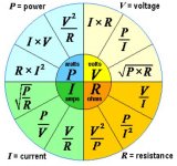
The current is calculated as I=V divided by R
If we placed another resistor of lets say 25 ohms across the same 5 volt circuit we would now still have 50 milliamps flowing the 100 ohm and 0.2 amps in the 25 ohm.
The total current coming out of the 5 volt source is now 0.25 amp (the total of the two)
If we now swap the circuit around and connect the two resistors in series (so they add together) and place that series combination across the 5 volts source we will see the 5 volts 'split' across the resistors in proportion to the resistor values.
So we now have 5 volts across 120 ohms.
The current through each resistor is identical because they are in a series circuit and that current is 5 divided by 120 (the total series resistance value) which is 41.66 milliamps.
The voltage across each resistor will now be 4.166 volts across the 100 ohm and 0.8332 across the 20 ohm.
Both calculated by multiplying the 41.6 milliamps (so that is 0.04166 amps) by each resistance value. Add the two voltages together and you get the total of 5 volts (ignoring rounding errors).
This might be useful:
So a 5 volt source... and we normally we would mean a voltage source which is something that provides 5 volts no matter what load we place on it would cause 5 volts to appear across the 100 ohm in your diagram and a current of 50 milliamps would flow through the resistor.
The current is calculated as I=V divided by R
If we placed another resistor of lets say 25 ohms across the same 5 volt circuit we would now still have 50 milliamps flowing the 100 ohm and 0.2 amps in the 25 ohm.
The total current coming out of the 5 volt source is now 0.25 amp (the total of the two)
If we now swap the circuit around and connect the two resistors in series (so they add together) and place that series combination across the 5 volts source we will see the 5 volts 'split' across the resistors in proportion to the resistor values.
So we now have 5 volts across 120 ohms.
The current through each resistor is identical because they are in a series circuit and that current is 5 divided by 120 (the total series resistance value) which is 41.66 milliamps.
The voltage across each resistor will now be 4.166 volts across the 100 ohm and 0.8332 across the 20 ohm.
Both calculated by multiplying the 41.6 milliamps (so that is 0.04166 amps) by each resistance value. Add the two voltages together and you get the total of 5 volts (ignoring rounding errors).
This might be useful:
Attachments
Well, "current only" is similar to looking at the size of a sheet of paper in terms of length only.
Ohm's Law describes the relationship of voltage and current in a resistor. If you have 1 ampere flowing through a 1 ohm resistor, then 1 volt will be dropped across that resistor. If you have 1 volt dropping across a resistor and measure 1 ampere flowing through, then you have a 1 ohm resistor. If I have 1v across a 1 ohm resistor, then 1 amp must be flowing through it.
Of course that is ideal. If you connect a 9v battery across a 1 ohm resistor, it might WANT to produce 9 amps, but it will not be able.
A practical example: a typical 12AX7 stage. a 100k plate resistor. If 1ma flows through it, 100v will be dropped across it. Or if we find the 300v supply drops 100v to the other end of the resistor, we know 1ma current is flowing.
I prefer to use the term "through" for current - current flows through something. I use the term across for voltage. VOltage is a difference between two points. As like the ends of a resistor. The resistor has 100v across it. End to end, like across a bridge it is 2 miles.
VOltage and current are forever linked. They do not mean the same thing, any more than length and width mean the same things.
- MoolySo a 5 volt source... and we normally we would mean a voltage source which is something that provides 5 volts no matter what load we place on it would cause 5 volts to appear across the 100 ohm in your diagram and a current of 50 milliamps would flow through the resistor.
That's a very important point. I have never seen anyone explain it this way, which is really too bad. That really clears things up. With computers it different, if a=5 then a=5 no matter what.
Common Emitter transistor circuit.
Thanks. My next set of questions are about the class A amplifier I am trying to build. I started with a simple class A circuit with one bias resistor and the speaker in series with the transistor. Since it was not good to have DC currents go through the speaker I used a transformer, but this set up is not satisfactory.
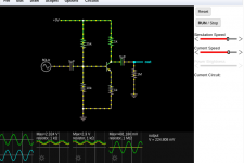
Looking up other audio circuits like the ones in John Audio Tech on You Tube, and the circuit in the Falstad Circuit simulator, I see a set of four resistors in the Common-Emitter circuit. I understand the circuit except for the two 'bottom' resistors.
When the current comes into the circuit, it splits into two parts, with the higher current going through the lower resistance. The top left hand resistor controls the flow of current, essentially taps the current from the current source and sends a little of it to the base of the transistor to push the transistor into operating levels as a small current is required to do this.
The top right hand resistor limits the current through the transistor, since when fully open current will flow unimpeded through the transistor and the wires, causing it to get very hot,essentially a short circuit.
The top right hand resistor is sometimes called a current source, with a large 10W ceramic resistor used : I understand this acts a current reservoir of some sort, is this correct and is ti largely due to the inductance of wire wound resistors, or simply resistance? How does a change in a downstream resistance in this case cause a less than proportional increase in current through the resistor?
I have uploaded the Falstad circuit diagram screenshot for reference. I changed the supply to 9V and the top resistors accordingly to preserve the same current.
Two more questions about the bottom two resistors.
I been searching for clear answers on You Tube and Google but it is all very technical.
Thanks. My next set of questions are about the class A amplifier I am trying to build. I started with a simple class A circuit with one bias resistor and the speaker in series with the transistor. Since it was not good to have DC currents go through the speaker I used a transformer, but this set up is not satisfactory.
Looking up other audio circuits like the ones in John Audio Tech on You Tube, and the circuit in the Falstad Circuit simulator, I see a set of four resistors in the Common-Emitter circuit. I understand the circuit except for the two 'bottom' resistors.
When the current comes into the circuit, it splits into two parts, with the higher current going through the lower resistance. The top left hand resistor controls the flow of current, essentially taps the current from the current source and sends a little of it to the base of the transistor to push the transistor into operating levels as a small current is required to do this.
The top right hand resistor limits the current through the transistor, since when fully open current will flow unimpeded through the transistor and the wires, causing it to get very hot,essentially a short circuit.
The top right hand resistor is sometimes called a current source, with a large 10W ceramic resistor used : I understand this acts a current reservoir of some sort, is this correct and is ti largely due to the inductance of wire wound resistors, or simply resistance? How does a change in a downstream resistance in this case cause a less than proportional increase in current through the resistor?
I have uploaded the Falstad circuit diagram screenshot for reference. I changed the supply to 9V and the top resistors accordingly to preserve the same current.
Two more questions about the bottom two resistors.
I been searching for clear answers on You Tube and Google but it is all very technical.
Attachments
Last edited:
Two more questions: A resistor is like restriction in a hosepipe, so squeezing the tune creates restriction to the flow.
Now imagine the bottom left resistor is a section of tube on a hydraulic circuit that can be squeezed. Squeezing the bottom left resistor will cause a restriction of flow in the entire tube, that is the entire wire from top to bottom. This causes more current to be diverted into the base of the transistor. But why place a resistor here? Why not simply decrease the resistance of the top left resistor?
Also the bottom right resistor - the same could be said, why the second resistor. I read it is for thermal stability, ok, by restricting the amplitude of the output using a resistor here, does it reduce the amplitude change due to thermal effects, is that how it works? Is there another reason for this resistor?
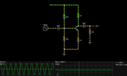
Also, the Falstad seems to generate a different simulation result for the same parameters:
Now imagine the bottom left resistor is a section of tube on a hydraulic circuit that can be squeezed. Squeezing the bottom left resistor will cause a restriction of flow in the entire tube, that is the entire wire from top to bottom. This causes more current to be diverted into the base of the transistor. But why place a resistor here? Why not simply decrease the resistance of the top left resistor?
Also the bottom right resistor - the same could be said, why the second resistor. I read it is for thermal stability, ok, by restricting the amplitude of the output using a resistor here, does it reduce the amplitude change due to thermal effects, is that how it works? Is there another reason for this resistor?
Also, the Falstad seems to generate a different simulation result for the same parameters:
Attachments
Learn-the-basics-FIRST.
Otherwise EVERY doubt you have will become a new Thread.
And you´ll have HUNDREDS.
Otherwise EVERY doubt you have will become a new Thread.
And you´ll have HUNDREDS.
Analogies like a resistor is like a squeeze on a hose may be useful to communicate an idea, but they break down when you try to apply them literally to a real circuit.
I agree with Juan, learn the basics. Otherwise you will keep taking one idea out of context and then try to squeeze other ideas into place around it.
Concepts you seem to be missing would include voltage dividers, parallel current paths, the operation of transistors, etc.
I agree with Juan, learn the basics. Otherwise you will keep taking one idea out of context and then try to squeeze other ideas into place around it.
Concepts you seem to be missing would include voltage dividers, parallel current paths, the operation of transistors, etc.
Much simplified but it will get you started.
The lower right hand resistor and the upper right one (the two 1k's) determine the gain of the circuit.
The collector resistor Rc and the emitter resistor Re work such that the gain is -Rc/Re. The minus means it inverts phase (which common emitter amplifiers do). So you have a gain of -1. As the input voltage rises the output falls and vice versa.
Try it. If you make the lower right resistor a 500 ohm then you will get twice as much signal at the output.
The two left hand resistors are there to pre-bias the transistor and set the 'operating point' such that the collector voltage sits at about 7 volts.
We can calculate those values once we decide (its our call) what collector voltage we want.
- Home
- General Interest
- Everything Else
- Questions about electric current and audio circuits.